Land Cruiser URJ200 URJ202 GRJ200 VDJ200 - 1GR-FE ENGINE CONTROL
READ VALUE USING GTS (ENGINE SPEED)
INSPECT CRANKSHAFT POSITION SENSOR (RESISTANCE)
CHECK HARNESS AND CONNECTOR (CRANKSHAFT POSITION SENSOR - ECM)
CHECK SENSOR INSTALLATION (CRANKSHAFT POSITION SENSOR)
CHECK CRANKSHAFT ANGLE SENSOR ROTOR (TEETH OF SENSOR ROTOR)
REPLACE CRANKSHAFT POSITION SENSOR
CHECK WHETHER DTC OUTPUT RECURS
DTC P0335 Crankshaft Position Sensor "A" Circuit
DTC P0339 Crankshaft Position Sensor "A" Circuit Intermittent
DESCRIPTION
The crankshaft position sensor system consists of a crankshaft angle sensor rotor and pickup coil.
The sensor rotor has 34 teeth and is installed to the crankshaft. The pickup coil is made of wound copper wire, an iron core and magnet. The sensor rotor rotates and, as each tooth passes by the pickup coil, a pulse signal is created. The pickup coil generates 34 signals per crankshaft revolution. Based on these signals, the ECM calculates the crankshaft position and engine speed. Using these calculations, the fuel injection time and ignition timing are controlled.
| DTC No. | DTC Detection Condition | Trouble Area |
| P0335 | Either condition is met: No crankshaft position sensor signal is sent to the ECM while cranking (1 trip detection logic). No crankshaft position sensor signal is sent to the ECM at an engine speed of 600 rpm or more (1 trip detection logic). | Open or short in crankshaft position sensor circuit Crankshaft position sensor Crankshaft angle sensor rotor ECM |
| P0339 | Under conditions (a), (b) and (c), no crankshaft position sensor signal is sent to the ECM for 0.05 seconds or more (1 trip detection logic): (a) Engine speed is 1000 rpm or more. (b) Starter signal is off. (c) 3 seconds or more have elapsed since the starter signal switched from on to off. | Open or short in crankshaft position sensor circuit Crankshaft position sensor Crankshaft angle sensor rotor ECM |
- HINT:
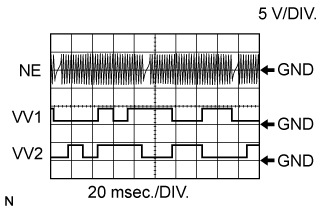
| Item | Content |
| Terminal | VV1+ - VV1- VV2+ - VV2- NE+ - NE- |
| Equipment Setting | 5 V/DIV., 20 msec./DIV. |
| Condition | Cranking or idling |
MONITOR DESCRIPTION
If there is no signal from the crankshaft position sensor despite the crankshaft revolving, the ECM interprets this as a malfunction of the sensor.
If the malfunction is not repaired successfully, a DTC is stored 10 seconds after the engine is next started.
WIRING DIAGRAM

INSPECTION PROCEDURE
- HINT:
- After performing the inspection procedure for the crankshaft position sensor, if DTC P0335 is output again, check the following items related to the VVT sensor.
- HINT:
| 1.READ VALUE USING GTS (ENGINE SPEED) |
Connect the GTS to the DLC3.
Turn the ignition switch to ON.
Turn the GTS on.
Enter the following menus: Powertrain / Engine and ECT / Data List / Engine Speed.
Start the engine.
Read the values displayed on the GTS while the engine is running.
- OK:
- Correct values are displayed.
- HINT:
|
| ||||
| OK | ||
| ||
| 2.INSPECT CRANKSHAFT POSITION SENSOR (RESISTANCE) |
Inspect the crankshaft position sensor ().
|
| ||||
| OK | |
| 3.CHECK HARNESS AND CONNECTOR (CRANKSHAFT POSITION SENSOR - ECM) |
Disconnect the crankshaft position sensor connector.
Disconnect the ECM connector.
Measure the resistance according to the value(s) in the table below.
- Standard Resistance:
for LHD Tester Connection Condition Specified Condition C1-1 - C45-110 (NE+) Always Below 1 Ω C1-2 - C45-111 (NE-) Always Below 1 Ω C1-1 or C45-110 (NE+) - Body ground Always 10 kΩ or higher C1-2 or C45-111 (NE-) - Body ground Always 10 kΩ or higher for RHD Tester Connection Condition Specified Condition C1-1 - C46-110 (NE+) Always Below 1 Ω C1-2 - C46-111 (NE-) Always Below 1 Ω C1-1 or C46-110 (NE+) - Body ground Always 10 kΩ or higher C1-2 or C46-111 (NE-) - Body ground Always 10 kΩ or higher
|
| ||||
| OK | |
| 4.CHECK SENSOR INSTALLATION (CRANKSHAFT POSITION SENSOR) |

Check the crankshaft position sensor installation.
- OK:
- Sensor is installed correctly.
|
| ||||
| OK | |
| 5.CHECK CRANKSHAFT ANGLE SENSOR ROTOR (TEETH OF SENSOR ROTOR) |
Check the teeth of the sensor rotor.
- OK:
- Sensor rotor teeth do not have any cracks or deformation.
|
| ||||
| OK | |
| 6.REPLACE CRANKSHAFT POSITION SENSOR |
Replace the crankshaft position sensor ().
| NEXT | |
| 7.CHECK WHETHER DTC OUTPUT RECURS |
Connect the GTS to the DLC3.
Turn the ignition switch to ON.
Turn the GTS on.
Clear the DTCs ().
Start the engine.
Enter the following menus: Powertrain / Engine and ECT / Trouble Codes.
Read the DTCs.
| Result | Proceed to |
| No DTC is output | A |
| P0335 or P0339 is output | B |
- HINT:
- If the engine does not start, replace the ECM.
|
| ||||
| A | ||
| ||