Engine Hybrid System. Land Cruiser. Urj200, 202 Grj200 Vdj200
1Vd-Ftv Engine Control. Land Cruiser. Urj200, 202 Grj200 Vdj200
Ecd System (W/ Dpf) -- Freeze Frame Data |
| DESCRIPTION |
- The ECM records vehicle and driving condition information as freeze frame data the moment a DTC is stored. When troubleshooting, freeze frame data can be helpful in determining whether the vehicle was moving or stationary, whether the air fuel ratio was lean or rich, as well as the other data recorded at the time of a malfunction.
- HINT:
- If it is impossible to duplicate the problem even though a DTC is stored, confirm the freeze frame data.
The ECM records engine conditions in the form of freeze frame data every 0.5 seconds. Using an GTS, 5 separate sets of freeze frame data can be checked.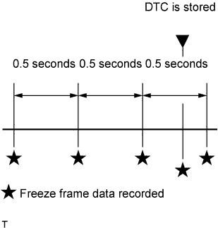
- 3 data sets from before the DTC was stored
- 1 data set from when the DTC was stored
- 1 data set from after the DTC was stored
- These data sets can be used to simulate the condition of the vehicle from around the time of the occurrence of the malfunction. The data may assist in identifying the cause of the malfunction, and in judging whether it was temporary or not.
| PENDING FREEZE FRAME DATA |
- HINT:
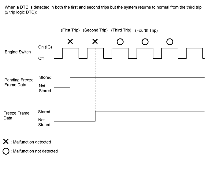
- Pending freeze frame data is stored when a 2 trip DTC is first detected during the first trip.
Connect the GTS to the DLC3.
Turn the engine switch on (IG).
Turn the GTS on.
Enter the following menus: Engine and ECT / Trouble Codes.
Select a DTC in order to display its pending freeze frame data.
- HINT:
- Pending freeze frame data is cleared when any of the following occurs.
- Using the GTS, the DTCs are cleared.
- The cable is disconnected from the negative (-) auxiliary battery terminal.
- 40 trips with the engine fully warmed up have been performed after returning to normal. (Pending freeze frame data will not be cleared by only returning the system to normal.)
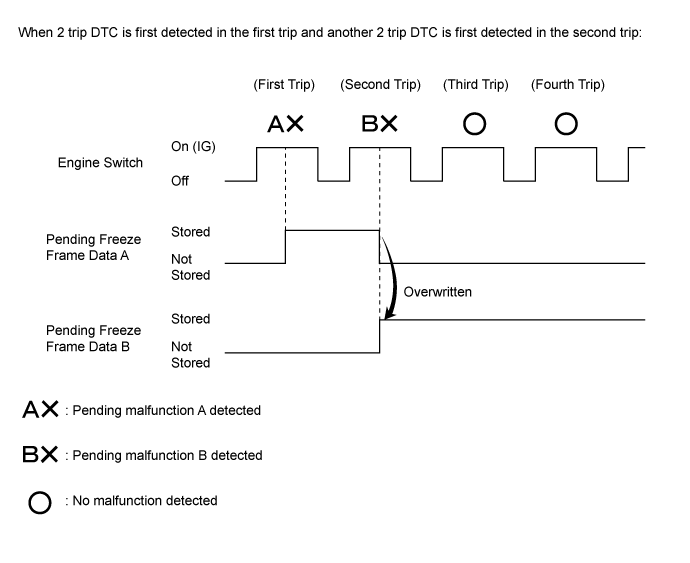
- With previous pending freeze frame data stored, if pending freeze frame data is newly stored when a 2 trip DTC is detected in the first trip, the old freeze frame data will be replaced with the new one of the newly detected DTC in the next trip.
| LIST OF FREEZE FRAME DATA |
| GTS Display | Measurement Item | Diagnostic Note |
| Vehicle Speed | Vehicle speed | The speed indicated on the speedometer. |
| Target Idle Engine Speed | Target idling speed | - |
| Engine Speed | Engine speed | - |
| Calculate Load | Calculated load | The load calculated by the ECM. |
| MAF | Mass air flow volume | If approximately 0.0 gm/sec:
|
| Atmosphere Pressure | Atmospheric pressure | - |
| MAP | Absolute pressure inside intake manifold | - |
| Coolant Temp | Engine coolant temperature | If -40°C (-40°F), the sensor circuit is open. If 140°C (284°F) or higher, the sensor circuit is shorted. |
| Intake Air | Intake air temperature | If -40°C (-40°F), the sensor circuit is open. If 140°C (284°F) or higher, the sensor circuit is shorted. |
| Intake Air Temp (Turbo) | Intake air temperature after intercooler | If -40°C (-40°F), the sensor circuit is open. If 190°C (374°F) or higher, the sensor circuit is shorted. |
| Engine Run Time | Accumulated engine running time | - |
| Initial Engine Coolant Temp | Engine coolant temperature at engine start | - |
| Initial Intake Air Temp | Intake air temperature at engine start | - |
| Battery Voltage | Battery voltage | - |
| Alternate Duty Ratio | Alternate duty ratio | - |
| Viscous Heater Stop Request | Viscous heater stop request | - |
| Glow Relay Request | Status of the glow relay request (bank 1) | - |
| Glow Relay Request #2 | Status of the glow relay request (bank 2) | - |
| Glow Indicator | Glow Indicator | - |
| Accel Position | Accelerator pedal position sensor | - |
| Accel Sens. No.1 Volt % | Accelerator pedal position No. 1 output voltage | - |
| Accel Sens. No.2 Volt % | Accelerator pedal position No. 2 output voltage | - |
| Target Throttle Position | Target throttle position (bank 1) | - |
| Target Throttle Position #2 | Target throttle position (bank 2) | - |
| Actual Throttle Position | Actual throttle position (bank 1) | - |
| Actual Throttle Position #2 | Actual throttle position (bank 2) | - |
| Throttle Motor DUTY | Throttle actuator (bank 1) | - |
| Throttle Motor DUTY #2 | Throttle actuator (bank 2) | - |
| Throttle Close Learning Val. | Throttle fully closed position learned value (bank 1) | - |
| Throttle Close Learning Val.#2 | Throttle fully closed position learned value (bank 2) | - |
| Throttle Sensor Volt % | Throttle position sensor output voltage (bank 1) | - |
| Throttl Sensor #2 Volt % | Throttle position sensor output voltage (bank 2) | - |
| Injection Volume | Injection volume | - |
| Inj. FB Vol. for Idle | Injection feedback value for idle speed control | - |
| Inj Vol Feedback Learning | Injection volume feedback learned value | - |
| Idle Signal Output Value | Idle signal output value (bank 1) | - |
| Idle Signal Output Value #2 | Idle signal output value (bank 2) | - |
| Injection Feedback Val #1 to Val #8 | Injection volume correction for cylinders 1 to 8 | - |
| Pilot 1 Injection Period | Pilot 1 injection period | - |
| Pilot 2 Injection Period | Pilot 2 injection period | - |
| Main Injection Period | Main injection period | - |
| After Injection Period | Post injection period | - |
| Pilot 1 Injection Timing | Pilot 1 injection timing | - |
| Pilot 2 Injection Timing | Pilot 2 injection timing | - |
| Main Injection Timing | Main injection timing | - |
| After Injection Timing | Post injection timing | - |
| Injector Pilot Quantity Learning | Pilot quantity learning status | The status is only displayed while performing "Pilot Quantity Learning". |
| Injection Pressure Correction | Injection pressure feedback compensation volume | - |
| Injection EDU Relay Request | Status of the EDU relay request (bank 1) | - |
| Injection EDU Relay Request #2 | Status of the EDU relay request (bank 2) | - |
| Target Common Rail Pressure | Target common rail pressure | - |
| Common Rail Pressure | Fuel pressure | - |
| Fuel Temperature | Fuel temperature | - |
| Target Pump SCV Current | Final pump current target value | - |
| Pump SCV Learning Value | Pump current learned value | - |
| Pump SCV Status | Pump SCV Status | - |
| Pump SCV Duty Request | Pump SCV duty request | - |
| Pressure Discharge Valve | Pressure discharge valve operation prohibition | - |
| AF Lambda B1S1 | Lambda equivalent ratio (bank 1) | - |
| AF Lambda B2S1 | Lambda equivalent ratio (bank 2) | - |
| AFS Voltage B1S1 | Air fuel ratio sensor output voltage (bank 1) | Performing control the injection volume or control the injection volume for air fuel ratio sensor function of Active Test enables technician to check output voltage of sensor |
| AFS Voltage B2S1 | Air fuel ratio sensor output voltage (bank 2) | Performing control the injection volume or control the injection volume for air fuel ratio sensor function of Active Test enables technician to check output voltage of sensor |
| AFS Current B1S1 | Air fuel ratio sensor output current (bank 1) | - |
| AFS Current B2S1 | Air fuel ratio sensor output current (bank 2) | - |
| AF Sensor Learning Value | Air fuel ratio sensor learning value (bank 1) | - |
| AF Sensor Learning Value #2 | Air fuel ratio sensor learning value (bank 2) | - |
| Target EGR Valve Pos | Target EGR valve position (No. 1) | - |
| Target EGR Valve Pos #2 | Target EGR valve position (No. 2) | - |
| Actual EGR Valve Pos | Actual EGR valve position (No. 1) | - |
| Actual EGR Valve Pos #2 | Actual EGR valve position (No. 2) | - |
| EGR Position Sensor | EGR Position Sensor position (No. 1) | - |
| EGR Position Sensor #2 | EGR Position Sensor position (No. 2) | - |
| EGR Motor Duty #1 | EGR motor duty ratio (No. 1) | - |
| EGR Motor Duty #2 | EGR motor duty ratio (No. 2) | - |
| EGR Close Lrn. Val. | EGR valve fully closed position learned value (No. 1) | - |
| EGR Close Lrn. Val. #2 | EGR valve fully closed position learned value (No. 2) | - |
| Target Booster Pressure | Target booster pressure | - |
| Target VN Turbo Position | Target VN turbo position (bank 1) | - |
| Target VN Turbo Position #2 | Target VN turbo position (bank 2) | - |
| Actual VN Turbo Position | Actual VN turbo position (bank 1) | - |
| Actual VN Turbo Position #2 | Actual VN turbo position (bank 2) | - |
| VN Position Sensor Out | VN position sensor output voltage (bank 1) | - |
| VN Position Sensor Out #2 | VN position sensor output voltage (bank 2) | - |
| VN Motor Duty | VN turbo motor duty (bank 1) | - |
| VN Motor Duty #2 | VN turbo motor duty (bank 2) | - |
| VN Close Learn Value | VN turbo fully closed position learned value (bank 1) | - |
| VN Close Learn Value #2 | VN turbo fully closed position learned value (bank 2) | - |
| VN Turbo Max Angle | VN turbo maximum opening amount | - |
| VN Turbo Min Angle | VN turbo minimum opening amount | - |
| Exhaust Temperature B1S1 | Exhaust temperature sensor (B1S1) | If 0°C (32°F), sensor circuit is open If 1000°C (1832°F) or more, sensor circuit is shorted |
| Exhaust Temperature B1S2 | No. 2 exhaust temperature sensor (B1S2) | If 0°C (32°F), sensor circuit is open If 1000°C (1832°F) or more, sensor circuit is shorted |
| Exhaust Temperature B1S3 | No. 4 exhaust temperature sensor (B1S3) | If 0°C (32°F), sensor circuit is open If 1000°C (1832°F) or more, sensor circuit is shorted |
| Exhaust Temperature B2S1 | Exhaust temperature sensor (B2S1) | If 0°C (32°F), sensor circuit is open If 1000°C (1832°F) or more, sensor circuit is shorted |
| Exhaust Temperature B2S2 | No. 3 exhaust temperature sensor (B2S2) | If 0°C (32°F), sensor circuit is open If 1000°C (1832°F) or more, sensor circuit is shorted |
| Exhaust Temperature B2S3 | No. 4 exhaust temperature sensor (B2S3) | If 0°C (32°F), sensor circuit is open If 1000°C (1832°F) or more, sensor circuit is shorted |
| DPF Differential Pressure | DPF differential pressure (bank 1) | - |
| DPF Differential Pressure #2 | DPF differential pressure (bank 2) | - |
| Diff. Press. Sensor Corr. | Differential pressure sensor 0 point learned value (bank 1) | - |
| Diff Press Sensor Corr #2 | Differential pressure sensor 0 point learned value (bank 2) | - |
| Exhaust Fuel Addition Injector Status | Status of the exhaust fuel addition injector status (bank 1) | - |
| Exhaust Fuel Addition Injector Status #2 | Status of the exhaust fuel addition injector status (bank 2) | - |
| Exhaust Fuel Addition FB | Exhaust fuel addition correction value (bank 1) | - |
| Exhaust Fuel Addition FB #2 | Exhaust fuel addition correction value (bank 2) | - |
| DPNR/DPF Status Reju(PM) | PM forced regeneration status | The status is only displayed while performing "Activate the DPF Rejuvenate (PM)" |
| PM Accumulation Ratio | PM accumulation ratio (bank 1) | - |
| PM Accumulation Ratio #2 | PM accumulation ratio (bank 2) | - |
| Starter Signal | Starter signal | - |
| Starter Control | Status of the starter control | - |
| Power Steering Signal | Power steering switch status | - |
| Starter Relay | Starter relay status | - |
| ACC Relay | ACC relay status | - |
| Neutral Position SW Signal | Neutral position switch signal | - |
| Transfer L4 | L4 status of the transfer | - |
| Stop Light Switch | Stop light switch | - |
| A/C Signal | Air conditioning signal | - |
| Idle Up Signal | Status of the idle up signal | - |
| Immobiliser Communication | Immobiliser communication | - |
| TC Terminal | TC terminal status | - |
| Time after DTC Cleared | Cumulative time after DTC cleared | - |
| Distance from DTC Cleared | Accumulated distance after DTC cleared | - |
| Warmup Cycle Cleared DTC | Warmup cycles after DTC cleared | - |
| Dist Batt Cable Disconnect | Distance driven after battery cable disconnected | - |
| IG OFF Elapsed Time | Time after engine switch turned off | - |
| TC and TE1 | TC and TE1 terminals of DLC3 | - |
| Engine Speed (Starter Off) | Engine speed when starter off | This item is used for troubleshooting when DTC P1604 is stored. |
| Starter Count | Starter on count | This item is used for troubleshooting when DTC P1604 is stored. |
| Run Dist of Previous Trip | Distance driven during previous trip | This item is used for troubleshooting when DTC P1604 is stored. |
| Glow Request Lighting Time | Glow request lighting time | This item is used for troubleshooting when DTC P1604 is stored. |
| IG-ON Time | Ignition switch ON time before engine start | This item is used for troubleshooting when DTC P1604 is stored. |
| MAF Low | Mass airflow low | This item is used for troubleshooting when DTC P1608 is stored. |
| Boost Pressure Low | Boost pressure low | This item is used for troubleshooting when DTC P1608 is stored. |
| Common Rail Pressure Low | Common rail pressure low | This item is used for troubleshooting when DTC P1608 is stored. |
| Engine Coolant Temp High | Engine coolant temperature high | This item is used for troubleshooting when DTC P1608 is stored. |
| MAF/Estimate MAF Ratio | Indicates the ratio of estimated intake air volume and the actual intake air volume | This item is used for troubleshooting when DTC P1608 is stored. |
| Rough Idle #1 to #8 | Rough idle status of cylinders 1 to 8 | This item is used for troubleshooting when DTC P1605 is stored. |
| Electric Duty Feedback Value | Electric load feedback value | - |
| A/C Duty Feedback Value | A/C load feedback value | - |
| Engine Starting Time | Engine starting time | - |
| Minimum Engine Speed | Minimum engine speed | - |
| ACM Inhibit | VSV for engine mount status | - |
| ACT VSV | A/C cut status for Active Test | - |
| Immobiliser Fuel Cut History | Status of the immobiliser fuel cut history | - |