Knock Sensor Installation
INSTALL KNOCK SENSOR
INSTALL NO. 1 ENGINE COVER
INSTALL NO. 2 ENGINE COVER
INSTALL SEPARATOR CASE
INSTALL NO. 3 ENGINE COVER
INSTALL NO. 4 ENGINE COVER
INSTALL NO. 1 EGR PIPE BRACKET
INSTALL NO. 1 WATER OUTLET PIPE
CONNECT NO. 11 WATER BY-PASS HOSE
CONNECT NO. 8 WATER BY-PASS HOSE
INSTALL NO. 2 WATER BY-PASS PIPE
INSTALL INTAKE MANIFOLD
Knock Sensor -- Installation |
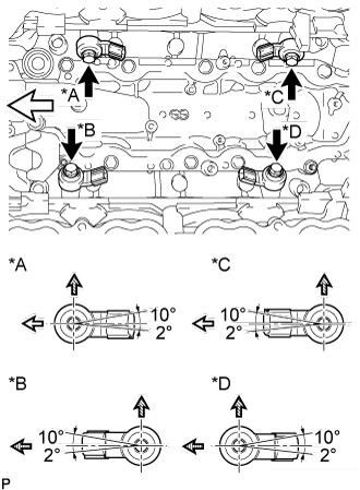
Install the 4 knock sensors with the 4 bolts so that the knock sensors are angled as shown in the illustration.
- Torque:
- 20 N*m{204 kgf*cm, 15 ft.*lbf}
Text in Illustration*A
| for Bank 2 Sensor 1
|
*B
| for Bank 1 Sensor 1
|
*C
| for Bank 2 Sensor 2
|
*D
| for Bank 1 Sensor 2
|

| Front
|
| Upper Side
|
| Rear
|
Connect the 4 knock sensor connectors.
| 2. INSTALL NO. 1 ENGINE COVER |
| 3. INSTALL NO. 2 ENGINE COVER |
| 4. INSTALL SEPARATOR CASE |
Install the separator case with the 4 bolts.
- Torque:
- 10 N*m{102 kgf*cm, 7 ft.*lbf}
| 5. INSTALL NO. 3 ENGINE COVER |
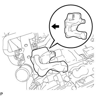
Install the No. 3 engine cover.
Text in Illustration
| Engine Front
|
- HINT:
- Position the No. 3 engine cover so that the arrow mark faces the front of the engine and install it.
| 6. INSTALL NO. 4 ENGINE COVER |
Install the No. 4 engine cover.
Text in Illustration
| Engine Front
|
- HINT:
- Position the No. 4 engine cover so that the arrow mark faces the front of the engine and install it.
| 7. INSTALL NO. 1 EGR PIPE BRACKET |
Install the No. 1 EGR pipe bracket with the 3 bolts.
- Torque:
- 21 N*m{214 kgf*cm, 15 ft.*lbf}
| 8. INSTALL NO. 1 WATER OUTLET PIPE |
Install the No. 1 water outlet pipe with the 2 bolts.
- Torque:
- 10 N*m{102 kgf*cm, 7 ft.*lbf}
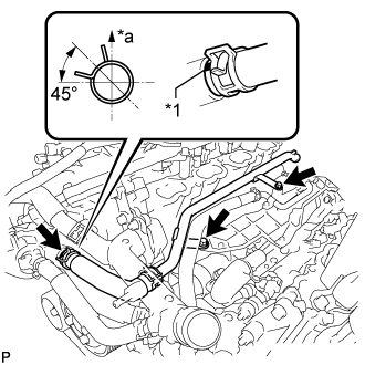
| 9. CONNECT NO. 11 WATER BY-PASS HOSE |
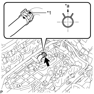
Connect the No. 11 water by-pass hose.
Text in Illustration*1
| Paint Mark
|
*a
| Upper Side
|
- HINT:
- The direction of the hose clamp is indicated in the illustration.
| 10. CONNECT NO. 8 WATER BY-PASS HOSE |
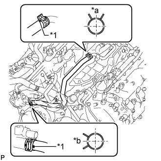
Install the No. 8 water by-pass hose.
Text in Illustration*1
| Paint Mark
|
*a
| Upper Side
|
*b
| Front
|
- HINT:
- When connecting the hose, make sure the paint marks and clips are as shown in the illustration.
- The direction of each hose clamp is indicated in the illustration.
| 11. INSTALL NO. 2 WATER BY-PASS PIPE |
Install the No. 2 water by-pass pipe with the 2 bolts and connect the hose.
- Torque:
- 10 N*m{102 kgf*cm, 7 ft.*lbf}
Text in Illustration*1
| Paint Mark
|
*a
| Upper Side
|
- HINT:
- When connecting the hose, make sure the paint marks and clips are as shown in the illustration.
- The direction of each hose clamp is indicated in the illustration.
| 12. INSTALL INTAKE MANIFOLD |
(Click here)