INSTALL CAMSHAFT TIMING OIL CONTROL VALVE ASSEMBLY (for Exhaust Side of Bank 2)
INSTALL CAMSHAFT TIMING OIL CONTROL VALVE ASSEMBLY (for Intake Side of Bank 2)
INSTALL CAMSHAFT TIMING OIL CONTROL VALVE ASSEMBLY (for Intake Side of Bank 1)
INSTALL CAMSHAFT TIMING OIL CONTROL VALVE ASSEMBLY (for Exhaust Side of Bank 1)
Camshaft Oil Control Valve -- Installation |
| 1. INSTALL CAMSHAFT TIMING OIL CONTROL VALVE ASSEMBLY (for Exhaust Side of Bank 2) |
Apply a light coat of engine oil to a new O-ring.
Install the O-ring to the camshaft timing oil control valve.
Install the camshaft timing oil control valve with the bolt.
- Torque:
- 10 N*m{102 kgf*cm, 7 ft.*lbf}
Connect the camshaft timing oil control valve connector.
| 2. INSTALL CAMSHAFT TIMING OIL CONTROL VALVE ASSEMBLY (for Intake Side of Bank 2) |
Apply a light coat of engine oil to a new O-ring.
Install the O-ring to the camshaft timing oil control valve.
Install the camshaft timing oil control valve with the bolt.
- Torque:
- 10 N*m{102 kgf*cm, 7 ft.*lbf}
Connect the camshaft timing oil control valve connector.
w/ Secondary Air Injection System:
Connect the air pipe with the bolt.
- Torque:
- 10 N*m{102 kgf*cm, 7 ft.*lbf}
Attach the clamp and connect the throttle body connector.
| 3. INSTALL CAMSHAFT TIMING OIL CONTROL VALVE ASSEMBLY (for Intake Side of Bank 1) |
Apply a light coat of engine oil to a new O-ring.
Install the O-ring to the camshaft timing oil control valve.
Install the camshaft timing oil control valve with the bolt.
- Torque:
- 10 N*m{102 kgf*cm, 7 ft.*lbf}
Connect the camshaft timing oil control valve connector.
| 4. INSTALL CAMSHAFT TIMING OIL CONTROL VALVE ASSEMBLY (for Exhaust Side of Bank 1) |
Apply a light coat of engine oil to a new O-ring.
Install the O-ring to the camshaft timing oil control valve.
Install the camshaft timing oil control valve with the bolt.
- Torque:
- 10 N*m{102 kgf*cm, 7 ft.*lbf}
Connect the camshaft timing oil control valve connector.
| 5. INSTALL AIR CLEANER CAP AND HOSE |
Install the air cleaner cap and hose, and then tighten the hose clamp.
- Torque:
- 2.5 N*m{25 kgf*cm, 22 in.*lbf}
Attach the 4 clamps.
Connect the mass air flow meter connector and attach the clamp.
Connect the No. 2 PCV hose and No. 1 air hose.
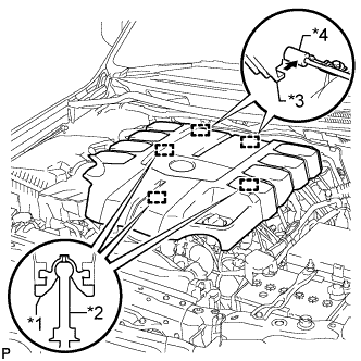
| 6. INSTALL V-BANK COVER SUB-ASSEMBLY |
Attach the 2 V-bank cover hooks to the bracket. Then align the 3 V-bank cover grommets with the 3 pins, and press down on the V-bank cover to attach the pins.
Text in Illustration *1 Grommet *2 Pin *3 Hook *4 Bracket
 |