Sfi System Acis Control Circuit
DESCRIPTION
WIRING DIAGRAM
INSPECTION PROCEDURE
PERFORM ACTIVE TEST USING GTS (OPERATE VACUUM SWITCHING VALVE FOR ACIS)
CHECK VACUUM HOSES (VACUUM SWITCHING VALVE (FOR ACIS) - INTAKE AIR CONTROL VALVE, INTAKE MANIFOLD)
INSPECT INTAKE MANIFOLD (INTAKE AIR CONTROL VALVE)
INSPECT VACUUM SWITCHING VALVE ASSEMBLY (FOR ACIS)
CHECK HARNESS AND CONNECTOR (VACUUM SWITCHING VALVE (FOR ACIS) - ECM AND NO. 1 INTEGRATION RELAY)
SFI SYSTEM - ACIS Control Circuit |
DESCRIPTION
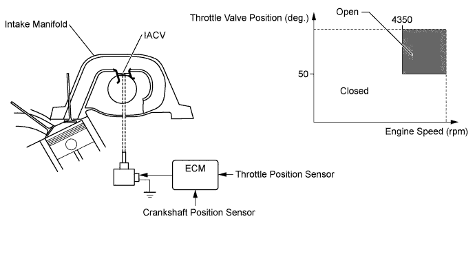
This circuit opens and closes the Intake Air Control Valve (IACV) in response to the engine load in order to increase the intake efficiency (ACIS: Acoustic Control Induction System).
WIRING DIAGRAM
Refer to DTC P0660 (Click here).
INSPECTION PROCEDURE
- NOTICE:
- Inspect the fuses for circuits related to this system before performing the following inspection procedure.
| 1.PERFORM ACTIVE TEST USING GTS (OPERATE VACUUM SWITCHING VALVE FOR ACIS) |
Disconnect the vacuum hose from port F on the vacuum switching valve (for ACIS).
Connect the GTS to the DLC3.
Start the engine.
Enter the following menus: Powertrain / Engine and ECT / Active Test / Activate the VSV for Intake Control.
Operate the vacuum switching valve for ACIS.
Check the vacuum switching valve air flow when switching the vacuum switching valve.
- OK:
Test Condition
| Specified Condition
|
Vacuum switching valve is ON
| Air from port E flows out through port F
|
Vacuum switching valve is OFF
| Air from port E flows out through air filter
|
Text in Illustration*a
| VSV is ON
|
*b
| VSV is OFF
|
*c
| Air
|
| 2.CHECK VACUUM HOSES (VACUUM SWITCHING VALVE (FOR ACIS) - INTAKE AIR CONTROL VALVE, INTAKE MANIFOLD) |
| | REPAIR OR REPLACE VACUUM HOSES |
|
|
| 3.INSPECT INTAKE MANIFOLD (INTAKE AIR CONTROL VALVE) |
Inspect the intake air control valve (Click here).
| OK |
|
|
|
| PROCEED TO NEXT SUSPECTED AREA SHOWN IN PROBLEM SYMPTOMS TABLE (Click here) |
|
| 4.INSPECT VACUUM SWITCHING VALVE ASSEMBLY (FOR ACIS) |
Inspect the vacuum switching valve assembly (for ACIS) (Click here).
| | REPLACE VACUUM SWITCHING VALVE ASSEMBLY (FOR ACIS) (Click here) |
|
|
| 5.CHECK HARNESS AND CONNECTOR (VACUUM SWITCHING VALVE (FOR ACIS) - ECM AND NO. 1 INTEGRATION RELAY) |
Disconnect the vacuum switching valve (for ACIS) connector.
Disconnect the ECM connector.
Remove the No. 1 integration relay from the engine room relay block.
Disconnect the No. 1 integration relay connector.
Measure the resistance according to the value(s) in the table below.
- Standard Resistance:
for RHDTester Connection
| Condition
| Specified Condition
|
C129-2 - C46-62 (ACIS)
| Always
| Below 1 Ω
|
C129-1 - 1B-4
| Always
| Below 1 Ω
|
C129-2 or C46-62 (ACIS) - Body ground
| Always
| 10 kΩ or higher
|
C129-1 or 1B-4 - Body ground
| Always
| 10 kΩ or higher
|
for LHDTester Connection
| Condition
| Specified Condition
|
C129-2 - C45-62 (ACIS)
| Always
| Below 1 Ω
|
C129-1 - 1B-4
| Always
| Below 1 Ω
|
C129-2 or C45-62 (ACIS) - Body ground
| Always
| 10 kΩ or higher
|
C129-1 or 1B-4 - Body ground
| Always
| 10 kΩ or higher
|
| | REPAIR OR REPLACE HARNESS OR CONNECTOR |
|
|