Dtc P0016 Crankshaft Position - Camshaft Position Correlation (Bank 1 Sensor A)
DESCRIPTION
MONITOR DESCRIPTION
WIRING DIAGRAM
INSPECTION PROCEDURE
CHECK FOR ANY OTHER DTCS OUTPUT (IN ADDITION TO DTC P0016 OR P0018)
PERFORM ACTIVE TEST USING GTS (OPERATE CAMSHAFT TIMING OIL CONTROL VALVE FOR INTAKE SIDE)
CHECK WHETHER DTC OUTPUT RECURS (DTC P0016 OR P0018)
CHECK VALVE TIMING (CHECK FOR LOOSE TEETH AND WHETHER TIMING CHAIN HAS JUMPED TOOTH)
INSPECT CAMSHAFT TIMING OIL CONTROL VALVE ASSEMBLY (FOR INTAKE SIDE)
CHECK OIL PIPE AND OIL CONTROL VALVE FILTER
REPLACE CAMSHAFT TIMING GEAR ASSEMBLY
CHECK WHETHER DTC OUTPUT RECURS (DTC P0016 OR P0018)
DTC P0016 Crankshaft Position - Camshaft Position Correlation (Bank 1 Sensor A) |
DTC P0018 Crankshaft Position - Camshaft Position Correlation (Bank 2 Sensor A) |
DESCRIPTION
In the VVT (Variable Valve Timing) system, the appropriate intake valve open and close timing is controlled by the ECM. The ECM performs intake valve control by performing the following: 1) controlling the camshaft and camshaft timing oil control valve, and operating the camshaft timing gear; and 2) changing the relative positions of the camshaft and crankshaft.DTC No.
| DTC Detection Condition
| Trouble Area
|
P0016
| Deviations in the crankshaft position sensor and VVT sensor 1 (for intake camshaft) signals (2 trip detection logic).
| - Valve timing
- Camshaft timing oil control valve assembly (for intake side)
- Oil control valve filter
- Camshaft timing gear assembly
- ECM
|
P0018
| Deviations in the crankshaft position sensor and VVT sensor 2 (for intake camshaft) signals (2 trip detection logic).
|
MONITOR DESCRIPTION
To monitor the correlation of the intake camshaft position and crankshaft position, the ECM checks the VVT learned value while the engine is idling. The VVT learned value is calibrated based on the camshaft position and crankshaft position. The intake valve timing is set to the most retarded angle while the engine is idling. If the VVT learned value is out of the specified range in consecutive driving cycles, the ECM illuminates the MIL and stores DTC P0016 (Bank 1) or P0018 (Bank 2).
WIRING DIAGRAM
Refer to DTC P0335 (Click here).Refer to DTC P0340 (Click here).
INSPECTION PROCEDURE
- HINT:
- Read freeze frame data using the GTS. Freeze frame data records the engine condition when malfunctions are detected. When troubleshooting, freeze frame data can help determine if the vehicle was moving or stationary, if the engine was warmed up or not, if the air-fuel ratio was lean or rich, and other data from the time the malfunction occurred.
- Bank 1 refers to the bank that includes the No. 1 cylinder*.
*: The No. 1 cylinder is the cylinder which is farthest from the transmission.
- Bank 2 refers to the bank that does not include the No. 1 cylinder.
| 1.CHECK FOR ANY OTHER DTCS OUTPUT (IN ADDITION TO DTC P0016 OR P0018) |
Connect the GTS to the DLC3.
Turn the ignition switch to ON and turn the GTS on.
Enter the following menus: Powertrain / Engine and ECT / Trouble Codes.
Read the DTCs.
ResultResult
| Proceed to
|
P0016 or P0018 is output
| A
|
P0016 or P0018 and other DTCs are output
| B
|
- HINT:
- If any DTCs other than P0016 or P0018 are output, troubleshoot those DTCs first.
| 2.PERFORM ACTIVE TEST USING GTS (OPERATE CAMSHAFT TIMING OIL CONTROL VALVE FOR INTAKE SIDE) |
Connect the GTS to the DLC3.
Start the engine and turn the GTS on.
Warm up the engine.
Turn the A/C on.
Enter the following menus: Powertrain / Engine and ECT / Active Test / Control the VVT Linear (Bank 1) or Control the VVT Linear (Bank 2).
Perform the Active Test. Check that the displacement angle varies.
- OK:
- Displacement angle varies.
| 3.CHECK WHETHER DTC OUTPUT RECURS (DTC P0016 OR P0018) |
Connect the GTS to the DLC3.
Turn the ignition switch to ON and turn the GTS on.
Clear the DTCs (Click here).
Start the engine and warm it up.
Switch the ECM from normal mode to check mode using the GTS (Click here).
Drive the vehicle for more than 10 minutes.
Read the DTCs using the GTS.
- OK:
- No DTC output.
| 4.CHECK VALVE TIMING (CHECK FOR LOOSE TEETH AND WHETHER TIMING CHAIN HAS JUMPED TOOTH) |
Remove the cylinder head cover RH and LH.
Text in Illustration*1
| Timing Mark
|
Turn the crankshaft pulley and align its groove with the "0" timing mark on the timing chain cover.
Check that the timing marks on the camshaft timing gears are aligned with the timing marks of the bearing cap as shown in the illustration.
- If not, turn the crankshaft 1 revolution (360°), and then align the marks as above.
- OK:
- Timing marks on camshaft timing gears are aligned as shown in the illustration.
| 5.INSPECT CAMSHAFT TIMING OIL CONTROL VALVE ASSEMBLY (FOR INTAKE SIDE) |
Inspect the camshaft timing oil control valve assembly (Click here).
| | REPLACE CAMSHAFT TIMING OIL CONTROL VALVE ASSEMBLY (Click here) |
|
|
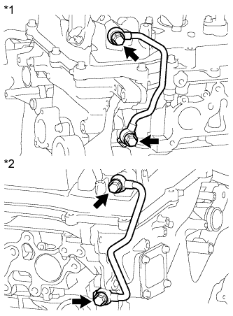
| 6.CHECK OIL PIPE AND OIL CONTROL VALVE FILTER |
Remove the No. 1 or No. 2 oil pipe.
Text in Illustration*1
| No. 1 Oil Pipe
|
*2
| No. 2 Oil Pipe
|
Remove the oil control valve filter.
Check that the filter and pipe are not clogged.
- OK:
- The filter and pipe are not clogged.
| | REPLACE OIL PIPE AND OIL CONTROL VALVE FILTER (Click here) |
|
|
| 7.REPLACE CAMSHAFT TIMING GEAR ASSEMBLY |
Replace the camshaft timing gear assembly (Click here).
| 8.CHECK WHETHER DTC OUTPUT RECURS (DTC P0016 OR P0018) |
Connect the GTS to the DLC3.
Turn the ignition switch to ON and turn the GTS on.
Clear the DTCs (Click here).
Start the engine and warm it up.
Switch the ECM from normal mode to check mode using the GTS (Click here).
Drive the vehicle for more than 10 minutes.
Confirm that no DTC is output using the GTS.
- OK:
- No DTC output.
- HINT:
- DTC P0016 or P0018 is stored when foreign objects in the engine oil are caught in some parts of the system. These codes will stay stored even if the system returns to normal after a short time. These foreign objects are then captured by the oil filter, thus eliminating the source of the problem.