Theft Deterrent System Driver Side Door Courtesy Switch Circuit
DESCRIPTION
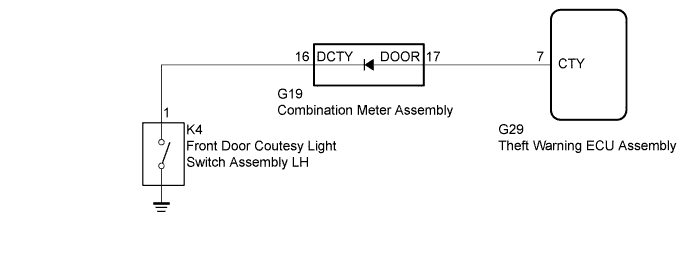
WIRING DIAGRAM
INSPECTION PROCEDURE
CHECK COMBINATION METER ASSEMBLY
CHECK HARNESS AND CONNECTOR (COMBINATION METER - THEFT WARNING ECU)
INSPECT FRONT DOOR COURTESY LIGHT SWITCH ASSEMBLY LH
CHECK HARNESS AND CONNECTOR (COMBINATION METER - FRONT DOOR COURTESY LIGHT SWITCH LH)
THEFT DETERRENT SYSTEM - Driver Side Door Courtesy Switch Circuit |
DESCRIPTION
The theft warning ECU assembly detects the condition of the front door courtesy light switch assembly LH.
WIRING DIAGRAM
INSPECTION PROCEDURE
| 1.CHECK COMBINATION METER ASSEMBLY |
When the driver side door is opened/closed, check that the indicator in the combination meter assembly operates normally.
- OK:
- Indicator operates normally.
| 2.CHECK HARNESS AND CONNECTOR (COMBINATION METER - THEFT WARNING ECU) |
Disconnect the G19 combination meter assembly connector.
Disconnect the G29 theft warning ECU assembly connector.
Measure the resistance according to the value(s) in the table below.
- Standard Resistance:
Tester Connection
| Condition
| Specified Condition
|
G19-17 (DOOR) - G29-7 (CTY)
| Always
| Below 1 Ω
|
G19-17 (DOOR) or G29-7 (CTY) - Body ground
| Always
| 10 kΩ or higher
|
Measure the voltage according to the value(s) in the table below.
- Standard Voltage:
Tester Connection
| Condition
| Specified Condition
|
G19-17 (DOOR) - Body ground
| Always
| 11 to 14 V
|
| | REPAIR OR REPLACE HARNESS OR CONNECTOR |
|
|
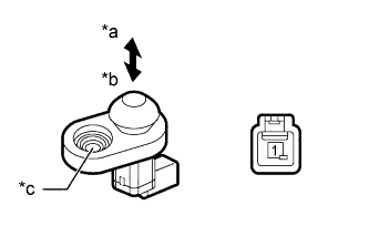
| 3.INSPECT FRONT DOOR COURTESY LIGHT SWITCH ASSEMBLY LH |
Remove the front door courtesy light switch assembly LH (HILUX_TGN26 RM000003YNE014X.html).
Measure the resistance according to the value(s) in the table below.
- Standard Resistance:
Tester Connection
| Switch Condition
| Specified Condition
|
1 - Body ground
| Not pushed (ON)
| Below 1 Ω
|
Pushed (OFF)
| 10 kΩ or higher
|
Text in Illustration*a
| Not pushed (ON)
|
*b
| Pushed (OFF)
|
*c
| Body ground
|
| 4.CHECK HARNESS AND CONNECTOR (COMBINATION METER - FRONT DOOR COURTESY LIGHT SWITCH LH) |
Disconnect the G19 combination meter assembly connector.
Disconnect the K4 front door courtesy light switch assembly LH connector.
Measure the resistance according to the value(s) in the table below.
- Standard Resistance:
Tester Connection
| Condition
| Specified Condition
|
G19-16 (DCTY) - K4-1
| Always
| Below 1 Ω
|
G19-16 (DCTY) or K4-1 - Body ground
| Always
| 10 kΩ or higher
|
| | REPAIR OR REPLACE HARNESS OR CONNECTOR |
|
|