Front Door Lock -- Removal |
- HINT:
- Use the same procedure for the RH and LH sides.
- The procedure listed below is for the LH side.
| 1. PRECAUTION |
- NOTICE:
- After turning the ignition switch off, waiting time may be required before disconnecting the cable from the battery terminal. Therefore, make sure to read the disconnecting the cable from the battery terminal notice before proceeding with work (HILUX_TGN26 RM000004QR1006X.html).
| 2. DISCONNECT CABLE FROM NEGATIVE BATTERY TERMINAL |
- NOTICE:
- When disconnecting the cable, some systems need to be initialized after the cable is reconnected (HILUX_TGN26 RM000004QR3008X.html).
| 3. REMOVE FRONT DOOR LOWER FRAME BRACKET GARNISH LH |
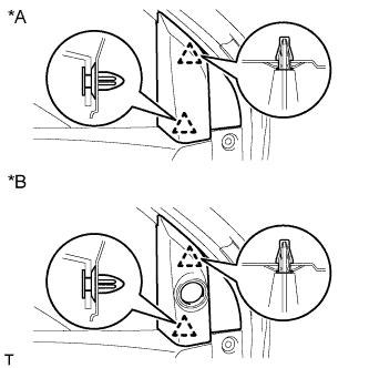
Detach the 2 clips and remove the front door lower frame bracket garnish.
Text in Illustration *A w/o Front No. 2 Speaker *B w/ Front No. 2 Speaker
 |
| 4. REMOVE DOOR PULL HANDLE |
Remove the screw and door pull handle.
 |
| 5. REMOVE POWER WINDOW REGULATOR MASTER SWITCH ASSEMBLY WITH FRONT DOOR ARMREST BASE PANEL (for Driver Side) |
Using a moulding remover, detach the 2 clips and 4 claws.
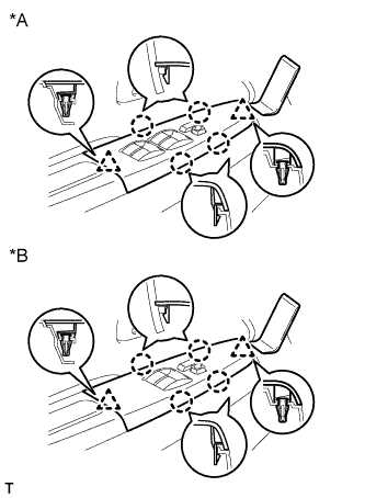 |
Disconnect the connector and remove the power window regulator master switch assembly with front door armrest base panel.
Text in Illustration *A for Double Cab *B for Single Cab
| 6. REMOVE POWER WINDOW REGULATOR SWITCH ASSEMBLY WITH FRONT DOOR ARMREST BASE PANEL (for Passenger Side) |
Using a moulding remover, detach the 2 clips and 4 claws.
 |
Disconnect the connector and remove the power window regulator switch assembly with front door armrest base panel.
| 7. REMOVE FRONT DOOR TRIM BOARD SUB-ASSEMBLY LH |
for Double Cab:
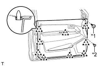
Remove the clip and screw.
Text in Illustration *1 Clip *2 Screw Detach the 8 clips and remove the front door trim board.
 |
for Single Cab:
Remove the clip and screw.
Text in Illustration *1 Clip *2 Screw Detach the 9 clips and remove the front door trim board.
 |
| 8. REMOVE FRONT DOOR INSIDE HANDLE SUB-ASSEMBLY LH |
Detach the claw and 2 guides as indicated by the arrows in the order shown in the illustration.
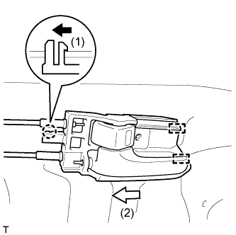 |
Disconnect the front door inside locking cable and front door lock remote control cable and remove the front door inside handle.
 |
| 9. REMOVE FRONT DOOR NO. 1 TRIM BRACKET |
Remove the 2 screws and front door No. 1 trim bracket.
 |
| 10. REMOVE FRONT DOOR SERVICE HOLE COVER LH |
Pull out the front door inside locking cable, front door lock remote control cable and wire harness from the front door service hole cover, and then remove the front door service hole cover.
- HINT:
- Remove any remaining butyl tape from the front door panel.
 |
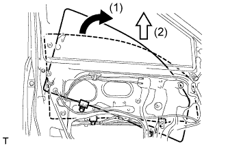
| 11. REMOVE FRONT DOOR GLASS SUB-ASSEMBLY LH |
w/ Power Window:
Temporarily install the power window regulator master switch assembly with front door armrest base panel.
Connect the cable to the negative (-) battery terminal.
Move the front door glass sub-assembly so that the front door glass bolts can be seen.
Disconnect the cable from the negative (-) battery terminal.
- NOTICE:
- When disconnecting the cable, some systems need to be initialized after the cable is reconnected (HILUX_TGN26 RM000004QR3008X.html).
Remove the power window regulator master switch assembly with front door armrest base panel.
w/o Power Window:
Temporarily install the door window regulator handle.
Move the front door glass sub-assembly so that the front door glass bolts can be seen.
Remove the door window regulator handle.
Remove the 2 bolts.
- NOTICE:
- After the bolts are removed, do not allow the front door glass to fall.
 |
Remove the front door glass as indicated by the arrows in the order shown in the illustration.
- NOTICE:
- Do not damage the front door glass.
 |
| 12. REMOVE FRONT DOOR REAR LOWER FRAME SUB-ASSEMBLY LH |
Remove the 2 nuts and front door rear lower frame.
 |
| 13. REMOVE FRONT DOOR OUTSIDE HANDLE COVER |
Remove the hole plug.
 |
Using a T30 "TORX" socket wrench, loosen the screw and remove the front door outside handle cover together with door key cylinder.
Detach the 2 claws and remove the front door outside handle cover from the door key cylinder.
 |
| 14. REMOVE FRONT DOOR LOCK ASSEMBLY LH |
Detach the claw and disconnect the front door lock remote control cable assembly from the door lock link clamp.
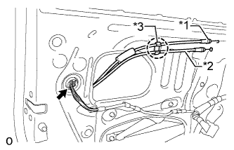 |
Detach the claw and disconnect the front door inside locking cable assembly from the door lock link clamp.
Text in Illustration *1 Front Door Inside Locking Cable Assembly LH *2 Front Door Lock Remote Control Cable Assembly *3 Door Lock Link Clamp
Disconnect the connector.
Using a T30 "TORX" wrench, remove the 3 screws.
 |
Slide the front door lock assembly downward, disconnect the front door lock assembly from the front door lock open rod, and remove the front door lock assembly and cables as a unit.
Remove the door lock wiring harness seal from the front door lock assembly.
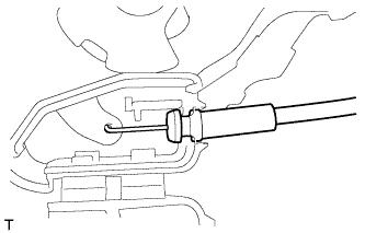
| 15. REMOVE FRONT DOOR INSIDE LOCKING CABLE ASSEMBLY LH |
Detach the 3 claws and open the cover.
 |
Remove the front door inside locking cable.
 |
| 16. REMOVE FRONT DOOR LOCK REMOTE CONTROL CABLE ASSEMBLY LH |
Remove the front door lock remote control cable.
 |