Can Communication System (W/ Vsc) -- Terminals Of Ecu |
- HINT:
- Operating the ignition switch, any switches or any doors triggers related ECU and sensor communication with the CAN, which causes resistance variation.
| DISCONNECT CABLE FROM NEGATIVE BATTERY TERMINAL |
Disconnect the cable from the negative (-) battery terminal before measuring the resistances of the CAN main wire and the CAN branch wire.
- CAUTION:
- Wait at least 90 seconds after disconnecting the cable from the negative (-) battery terminal to disable the SRS system.
- NOTICE:
- Before measuring the resistance, leave the vehicle for at least 1 minute and do not operate the ignition switch, any switches or any doors. If doors need to be opened in order to check connectors, open the doors and leave them open.
- After turning the ignition switch off, waiting time may be required before disconnecting the cable from the battery terminal. Therefore, make sure to read the disconnecting the cable from the battery terminal notice before proceeding with work (HILUX_TGN26 RM000004QR1006X.html).
- When disconnecting the cable, some systems need to be initialized after the cable is reconnected (HILUX_TGN26 RM000004QR3009X.html).
| JUNCTION CONNECTOR |
NO. 1 JUNCTION CONNECTOR
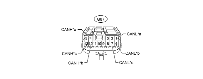
Text in Illustration *a for No. 2 Junction Connector *b for ECM (V Bus) *c for Brake Actuator Assembly (Skid Control ECU) - - No. 1 Junction Connector Wiring Color Connect to G87-4 (CANH) B No. 2 junction connector G87-1 (CANL) W G87-12 (CANH) B ECM (V bus) G87-6 (CANL) W G87-13 (CANH) R Brake actuator assembly (skid control ECU) G87-7 (CANL) W NO. 2 JUNCTION CONNECTOR

Text in Illustration *a for No. 1 Junction Connector *b for No. 3 Junction Connector *c for Yaw Rate Sensor Assembly - - No. 2 Junction Connector Wiring Color Connect to G86-5 (CANH) B No. 1 junction connector G86-16 (CANL) W G86-6 (CANH) B No. 3 junction connector G86-17 (CANL) W G86-7 (CANH) R Yaw rate sensor assembly G86-18 (CANL) W NO. 3 JUNCTION CONNECTOR
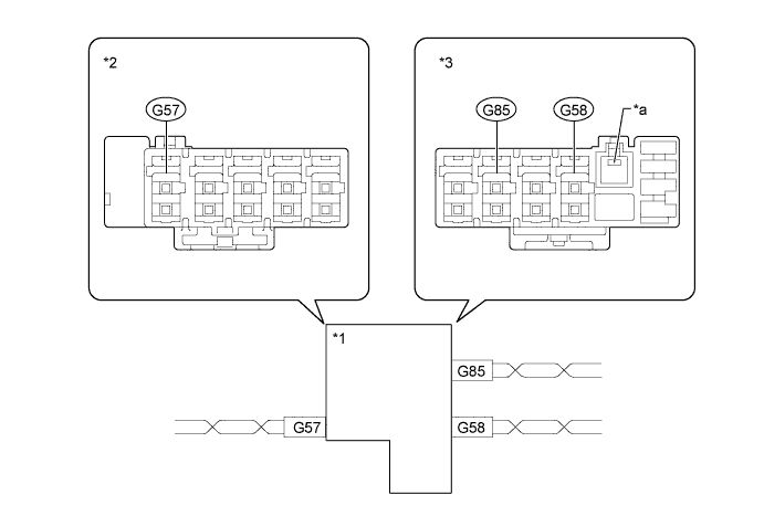
Text in Illustration *1 No. 3 Junction Connector *2 Junction Connector A Side *3 Junction Connector B Side - - *a Ground Terminal - - Junction Connector A Side Wiring Color (CANH Side) Wiring Color (CANL Side) DLC3 (G57) R W Junction Connector B Side Wiring Color (CANH Side) Wiring Color (CANL Side) No. 2 Junction Connector (G58) B W Spiral Cable Sub-assembly (Steering Angle Sensor) (G85) R W
| CHECK DLC3 |
Disconnect the cable from the negative (-) battery terminal before measuring the resistances of the CAN main wire and the CAN branch wire.
- CAUTION:
- Wait at least 90 seconds after disconnecting the cable from the negative (-) battery terminal to disable the SRS system.
- NOTICE:
- After turning the ignition switch off, waiting time may be required before disconnecting the cable from the battery terminal. Therefore, make sure to read the disconnecting the cable from the battery terminal notice before proceeding with work (HILUX_TGN26 RM000004QR1006X.html).
- When disconnecting the cable, some systems need to be initialized after the cable is reconnected (HILUX_TGN26 RM000004QR3009X.html).
Measure the resistance according to the value(s) in the table below.
Terminal No. (Symbol) Wiring Color Switch Condition Specified Condition G18-6 (CANH) - G18-14 (CANL) R - W Ignition switch off 54 to 69 Ω G18-6 (CANH) - G18-4 (CG) R - G Ignition switch off 200 Ω or higher G18-14 (CANL) - G18-4 (CG) W - G Ignition switch off 200 Ω or higher G18-6 (CANH) - G18-16 (BAT) R - G Ignition switch off 6 kΩ or higher G18-14 (CANL) - G18-16 (BAT) W - G Ignition switch off 6 kΩ or higher
 |
| CHECK ECM |
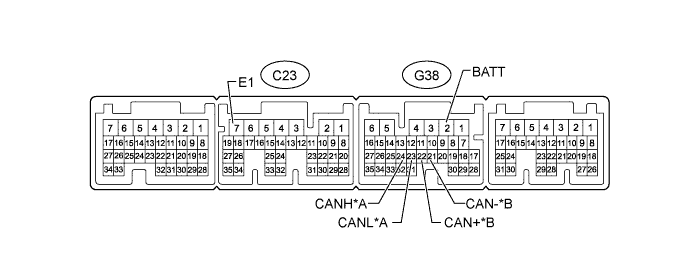
| *A | for V Bus | *B | for Powertrain Bus |
Disconnect the C23 and G38 ECM connectors.
Measure the resistance according to the value(s) in the table below.
for V Bus Terminal No. (Symbol) Wiring Color Switch Condition Specified Condition G38-24 (CANH) - G38-23 (CANL) B - W Ignition switch off 108 to 132 Ω G38-24 (CANH) - C23-7 (E1) B - BR Ignition switch off 200 Ω or higher G38-23 (CANL) - C23-7 (E1) W - BR Ignition switch off 200 Ω or higher G38-24 (CANH) - G38-2 (BATT) B - L Ignition switch off 6 kΩ or higher G38-23 (CANL) - G38-2 (BATT) W - L Ignition switch off 6 kΩ or higher for Powertrain Bus Terminal No. (Symbol) Wiring Color Switch Condition Specified Condition G38-22 (CAN+) - G38-21 (CAN-) V - P Ignition switch off 108 to 132 Ω G38-22 (CAN+) - C23-7 (E1) V - BR Ignition switch off 200 Ω or higher G38-21 (CAN-) - C23-7 (E1) P - BR Ignition switch off 200 Ω or higher G38-22 (CAN+) - G38-2 (BATT) V - L Ignition switch off 6 kΩ or higher G38-21 (CAN-) - G38-2 (BATT) P - L Ignition switch off 6 kΩ or higher
| CHECK BRAKE ACTUATOR ASSEMBLY (SKID CONTROL ECU) |
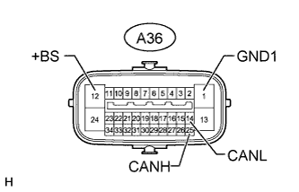 |
Disconnect the A36 brake actuator assembly (skid control ECU) connector.
Measure the resistance according to the value(s) in the table below.
Terminal No. (Symbol) Wiring Color Switch Condition Specified Condition A36-25 (CANH) - A36-14 (CANL) B - W Ignition switch off 54 to 69 Ω A36-25 (CANH) - A36-1 (GND1) B - W-B Ignition switch off 200 Ω or higher A36-14 (CANL) - A36-1 (GND1) W - W-B Ignition switch off 200 Ω or higher A36-25 (CANH) - A36-12 (+BS) B - W-R Ignition switch off 6 kΩ or higher A36-14 (CANL) - A36-12 (+BS) W - W-R Ignition switch off 6 kΩ or higher
| CHECK SPIRAL CABLE SUB-ASSEMBLY (STEERING ANGLE SENSOR) |
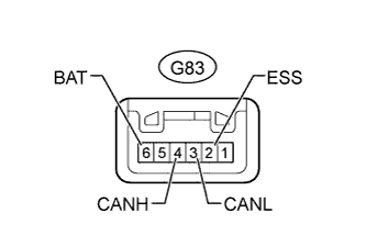 |
Disconnect the G83 spiral cable sub-assembly (steering angle sensor) connector.
Measure the resistance according to the value(s) in the table below.
Terminal No. (Symbol) Wiring Color Switch Condition Specified Condition G83-4 (CANH) - G83-3 (CANL) R - W Ignition switch off 54 to 69 Ω G83-4 (CANH) - G83-2 (ESS) R - W-B Ignition switch off 200 Ω or higher G83-3 (CANL) - G83-2 (ESS) W - W-B Ignition switch off 200 Ω or higher G83-4 (CANH) - G83-6 (BAT) R - B Ignition switch off 6 kΩ or higher G83-3 (CANL) - G83-6 (BAT) W - B Ignition switch off 6 kΩ or higher
| CHECK YAW RATE SENSOR ASSEMBLY |

Disconnect the K21 yaw rate sensor assembly connector.
Measure the resistance according to the value(s) in the table below.
Terminal No. (Symbol) Wiring Color Switch Condition Specified Condition K21-3 (CANH) - K21-2 (CANL) B - W Ignition switch off 54 to 69 Ω K21-3 (CANH) - K21-1 (GND) B - W-B Ignition switch off 200 Ω or higher K21-2 (CANL) - K21-1 (GND) W - W-B Ignition switch off 200 Ω or higher K21-3 (CANH) - G18-16 (BAT) B - G Ignition switch off 6 kΩ or higher K21-2 (CANL) - G18-16 (BAT) W - G Ignition switch off 6 kΩ or higher
| CHECK TRANSMISSION CONTROL ECU ASSEMBLY (TCM) |
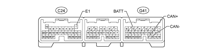
Disconnect the C24 and G41 transmission control ECU assembly (TCM) connectors.
Measure the resistance according to the value(s) in the table below.
Terminal No. (Symbol) Wiring Color Switch Condition Specified Condition G41-21 (CAN+) - G41-20 (CAN-) V - P Ignition switch off 108 to 132 Ω G41-21 (CAN+) - C24-1 (E1) V - BR Ignition switch off 200 Ω or higher G41-20 (CAN-) - C24-1 (E1) P - BR Ignition switch off 200 Ω or higher G41-21 (CAN+) - G41-5 (BATT) V - L Ignition switch off 6 kΩ or higher G41-20 (CAN-) - G41-5 (BATT) P - L Ignition switch off 6 kΩ or higher