Steering Gear -- Reassembly |
- NOTICE:
- When using a vise, place aluminum plates between the part and vise.
- When using a vise, do not overtighten it.
- HINT:
- Use the same procedure for RHD and LHD vehicles.
- The procedure listed below is for LHD vehicles.
| 1. INSTALL POWER STEERING CYLINDER TUBE OIL SEAL |
Install the spacer to the power steering rack housing.
- NOTICE:
- Do not damage the inside of the power steering rack housing.
Apply power steering fluid to the lip of a new power steering cylinder tube oil seal.
Install the power steering cylinder tube oil seal to the rack housing at an angle.
- NOTICE:
- Make sure that the power steering cylinder tube oil seal is installed in the correct direction as shown in the illustration.
- Install the power steering cylinder tube oil seal at an angle of approximately 20° so that the lowermost part comes to the point indicated by the arrow in the illustration to prevent damage to the oil seal when it passes the 2 ports.
- After passing both ports, proceed by pressing the oil at an angle of 10° and 0° sequentially.
 |
Using SST, push in the power steering cylinder tube oil seal until the oil seal passes the 2 ports.
- SST
- 09631-00200
09950-70010(09951-07360)
- NOTICE:
- Do not turn SST when inserting the oil seal.
- Do not use any tools other than SST.
Install SST (09631-00200) to SST (09951-07360) upside down.
- SST
- 09631-00200
09950-70010(09951-07360)
Using SST, push the power steering cylinder tube oil seal so that it is level.
- SST
- 09631-00200
09950-70010(09951-07360)
- NOTICE:
- Do not use any tools other than SST.
Using SST and a press, install the power steering cylinder tube oil seal.
- SST
- 09631-00200
09950-70010(09951-07360)
- HINT:
- Press the cylinder tube oil seal until it sits on the stopper portion.
 |
| 2. INSTALL "TEFLON" RING |
Coat a new O-ring with power steering fluid and install it to the steering rack.
Stretch a new "Teflon" ring with your fingers.
- NOTICE:
- Be careful not to overstretch the "Teflon" ring.
 |
Coat the "Teflon" ring with power steering fluid.
Install the "Teflon" ring to the groove of the steering rack. Grip the ring to press it into the groove.
 |
| 3. INSTALL POWER STEERING RACK |
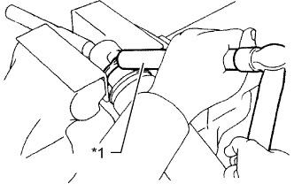
Apply grease to the rack teeth ends.
Text in Illustration *1 Rack Teeth End
 |
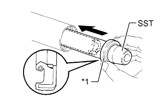
Install SST to the steering rack.
- SST
- 09631-00350
- HINT:
- If necessary, scrape the burrs off the rack teeth ends and burnish them.
Coat SST with power steering fluid.
Install the steering rack to the rack housing.
Remove SST.
Install a new bush to the steering rack.
Coat SST with power steering fluid.
- SST
- 09631-00350
Text in Illustration *1 Oil Seal
 |
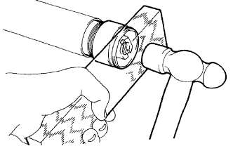
Install SST to the opposite end of the steering rack.
Coat the lip of a new oil seal with power steering fluid. Using SST, install the oil seal to the steering rack.
- NOTICE:
- Slide SST and the oil seal straight without tilting them.
- Make sure that the oil seal is facing the correct direction.
- Be careful not to damage the lip of the oil seal.
Remove SST.
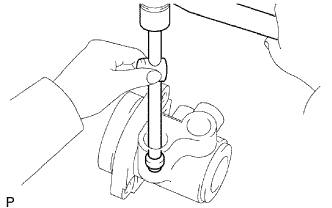
| 4. INSTALL CYLINDER END STOPPER |
Apply sealant to the stopper.
Using a wooden block and hammer, tap in the stopper until it is securely installed.
- Adhesive:
- Toyota Genuine Adhesive 1344, Three Bond 1344 or equivalent
 |
Using SST, tighten the stopper.
- SST
- 09631-20120
- Torque:
- 83 N*m{841 kgf*cm, 61 ft.*lbf}
 |
| 5. TEST AIRTIGHTNESS |
Install SST to the unions of the rack housing.
- SST
- 09631-12071(09633-00010)
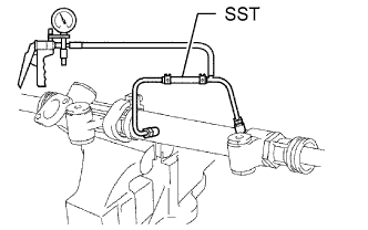 |
Apply 53 kPa (400 mmHg, 15.75 in.Hg) of vacuum for about 30 seconds.
Check that there is no change in the vacuum.
If there is a change in the vacuum, check the installation of the oil seals.
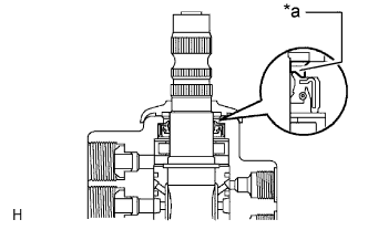
| 6. INSTALL POWER STEERING CONTROL VALVE |
Apply molybdenum disulfide lithium base grease to the needle roller bearing inside the rack housing shown in the illustration.
Text in Illustration *a Apply Molybdenum Disulfide Lithium Base Grease - Volume of grease applied:
- Approximately 2 g (0.07 oz)
 |
Using a plastic-faced hammer and sliding handle, lightly tap in 2 new union seats.
- NOTICE:
- Before installing the union seat, remove any adhering to the control valve housing.
 |
Install a new control valve gasket and the control valve with the 2 bolts.
- Torque:
- 18 N*m{185 kgf*cm, 13 ft.*lbf}
 |
Apply MP grease as shown in the illustration.
Text in Illustration *a Grease Filling
 |
| 7. INSTALL RACK GUIDE |
Install the rack guide and spring.
Apply sealant to 2 or 3 threads of the spring cap.
- Adhesive:
- Toyota Genuine Adhesive 1344, Three Bond 1344 or equivalent
Using a 12 mm socket wrench, temporarily install the spring cap.
Text in Illustration *1 12 mm Socket Wrench
 |
| 8. ADJUST TOTAL PRELOAD |
To prevent the steering rack teeth from damaging the lip of the oil seal, temporarily install the RH and LH rack ends.
Using a 12 mm socket wrench, tighten the spring cap.
- Torque:
- 25 N*m{250 kgf*cm, 18 ft.*lbf}
Loosen the spring cap 30°.
Text in Illustration *1 12 mm Socket Wrench
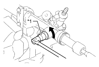 |
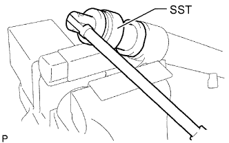
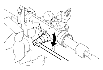
Using SST, turn the control valve shaft right and left 1 or 2 times. The rack end will move in and out.
- SST
- 09616-00011
 |
Loosen the spring cap until the rack guide spring does not function.
Using SST, a torque wrench and a 12 mm socket wrench, tighten the spring cap until the preload is within the specification.
- SST
- 09616-00011
Text in Illustration *1 12 mm Socket Wrench - Standard preload (turning):
- 1.0 to 1.8 N*m (11 to 18 kgf*cm, 9 to 15 in.*lbf)
- NOTICE:
- Perform adjustments by tightening the spring cap. Do not loosen the spring cap.
 |
Apply sealant to 2 or 3 threads of the lock nut.
- Adhesive:
- Toyota Genuine Adhesive 1344, Three Bond 1344 or equivalent
Temporarily install the lock nut.
Using a 12 mm socket wrench, hold the spring cap. Using SST, tighten the lock nut.
- SST
- 09922-10010
Text in Illustration *1 12 mm Socket Wrench *a Hold *b Turn - Torque:
- without SST:
- 69 N*m{700 kgf*cm, 51 ft.*lbf}
- with SST:
- 51 N*m{516 kgf*cm, 37 ft.*lbf}
- HINT:
- Use a torque wrench with a fulcrum length of 345 mm (13.58 in.).
- The torque value for use with SST is effective when SST is parallel to the torque wrench.
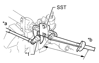 |
Using SST, recheck the total preload.
- SST
- 09616-00011
- Standard preload (turning):
- 1.0 to 1.8 N*m (11 to 18 kgf*cm, 9 to 15 in.*lbf)
 |
Remove the RH and LH rack ends.
| 9. INSPECT POWER STEERING RACK |
Insert a wire 20 mm (0.787 in.) into the vent hole of the steering rack, and make sure that the vent hole is not clogged with grease.
- NOTICE:
- If the hole is clogged, the pressure inside the boot will change after the boot is assembled and the steering wheel is turned.
 |
| 10. INSTALL STEERING RACK END SUB-ASSEMBLY |
Install a new claw washer to each steering rack end while aligning the claw of the claw washer with the notch on the steering rack end.
 |
Temporarily install the 2 steering rack ends to the power steering rack.
Fill up the ball joint of each steering rack end with MP grease.
Using SST, install the power steering rack end (RH side) to the power steering rack.
- SST
- 09922-10010
Text in Illustration *A for RH Side *B for LH Side *1 Wrench *a Hold *b Turn - Torque:
- without SST:
- 103 N*m{1050 kgf*cm, 76 ft.*lbf}
- with SST:
- 75 N*m{765 kgf*cm, 55 ft.*lbf}
- HINT:
- Rotate SST in the direction shown in the illustration.
- Use a torque wrench with a fulcrum length of 345 mm (13.6 in.).
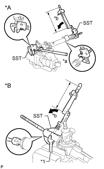 |
Using SST and a wrench, install the power steering rack end (LH side) to the power steering rack.
- SST
- 09922-10010
- Torque:
- without SST:
- 103 N*m{1050 kgf*cm, 76 ft.*lbf}
- with SST:
- 75 N*m{765 kgf*cm, 55 ft.*lbf}
- HINT:
- Rotate SST in the direction shown in the illustration.
- Use a torque wrench with a fulcrum length of 345 mm (13.6 in.).
Using a brass bar and hammer, stake the 2 claw washers (LH and RH side).
Text in Illustration *1 Brass Bar - NOTICE:
- Do not strike the steering rack.
 |
| 11. INSTALL STEERING RACK BOOT LH |
Install the boot.
- NOTICE:
- Be careful not to damage or twist the boot.
| 12. INSTALL STEERING RACK BOOT RH |
- HINT:
- Use the same procedure described for the LH side.
| 13. INSTALL STEERING RACK BOOT CLAMP LH |
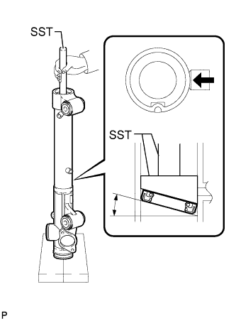
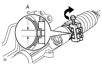
Using SST, install a new rack boot clamp as shown in the illustration.
- SST
- 09240-00020
09521-24010
- Standard clearance (A):
- 3.0 mm (0.118 in.) or less
- NOTICE:
- Be careful not to damage the boot.
 |
| 14. INSTALL STEERING RACK BOOT CLAMP RH |
- HINT:
- Use the same procedure described for the LH side.
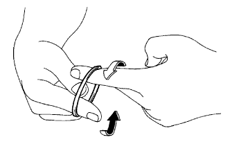
| 15. INSTALL STEERING RACK BOOT CLIP LH |
Using pliers, install the clip.
| 16. INSTALL STEERING RACK BOOT CLIP RH |
- HINT:
- Use the same procedure described for the LH side.
| 17. INSPECT POWER STEERING LINK ASSEMBLY |
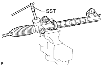
Using SST, check that the rack boot stretches smoothly when the control valve shaft is being rotated.
- SST
- 09616-00011
 |
| 18. INSTALL STEERING TURN PRESSURE TUBE |
Apply power steering fluid to 4 new O-rings, and install the O-rings to the turn pressure tubes.
Using a union nut wrench, install the 2 turn pressure tubes.
- Torque:
- 13 N*m{127 kgf*cm, 9 ft.*lbf}
- NOTICE:
- Use the formula to calculate special torque values for situations where a union nut wrench is combined with a torque wrench (HILUX_TGN26 RM000004QR1003X.html).
| 19. INSTALL TIE ROD END SUB-ASSEMBLY LH |
Screw the lock nut and tie rod end onto the rack end until the matchmarks are aligned.
After adjusting the toe-in, tighten the nut.
- Torque:
- 56 N*m{571 kgf*cm, 41 ft.*lbf}
| 20. INSTALL TIE ROD END SUB-ASSEMBLY RH |
- HINT:
- Use the same procedure described for the LH side.