INSPECT 1ST DRIVEN GEAR THRUST CLEARANCE
INSPECT 1ST DRIVEN GEAR RADIAL CLEARANCE
INSPECT 2ND DRIVEN GEAR THRUST CLEARANCE
INSPECT 2ND DRIVEN GEAR RADIAL CLEARANCE
INSPECT 3RD DRIVEN GEAR THRUST CLEARANCE
INSPECT 3RD DRIVEN GEAR RADIAL CLEARANCE
INSPECT 4TH DRIVEN GEAR THRUST CLEARANCE
INSPECT 4TH DRIVEN GEAR RADIAL CLEARANCE
REMOVE OUTPUT SHAFT BEARING SHAFT SNAP RING
REMOVE OUTPUT SHAFT FRONT BEARING
REMOVE 3RD DRIVEN GEAR
REMOVE SPACER
REMOVE NEEDLE ROLLER BEARING
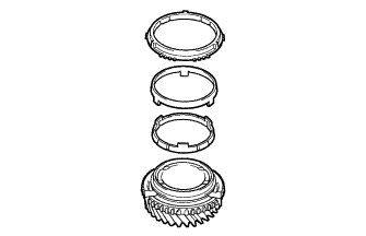
REMOVE 3RD DRIVEN GEAR SYNCHRONIZER RING SET
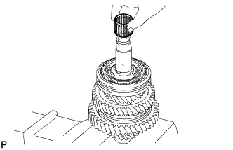
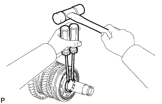
REMOVE SHAFT SNAP RING
REMOVE 4TH DRIVEN GEAR
REMOVE 4TH DRIVEN GEAR SYNCHRONIZER RING SET
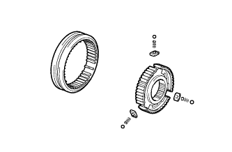
REMOVE NO. 2 TRANSMISSION CLUTCH HUB
REMOVE NEEDLE ROLLER BEARING
REMOVE SPACER
REMOVE OUTPUT SHAFT BEARING SHAFT SNAP RING
REMOVE 2ND GEAR BEARING INNER RACE
REMOVE 2ND DRIVEN GEAR
REMOVE NEEDLE ROLLER BEARING
REMOVE SYNCHROMESH SHIFTING KEY BALL
REMOVE 2ND DRIVEN GEAR SYNCHRONIZER RING SET
REMOVE 1ST DRIVEN GEAR
REMOVE 1ST DRIVEN GEAR SYNCHRONIZER RING SET
REMOVE NO. 1 TRANSMISSION CLUTCH HUB
REMOVE NEEDLE ROLLER BEARING
REMOVE OUTPUT SHAFT FRONT BEARING SHAFT SNAP RING
REMOVE OUTPUT SHAFT FRONT BEARING
INSPECT 5TH DRIVEN GEAR THRUST CLEARANCE
INSPECT 5TH DRIVEN GEAR RADIAL CLEARANCE
INSPECT 6TH DRIVEN GEAR THRUST CLEARANCE
INSPECT 6TH DRIVEN GEAR RADIAL CLEARANCE
INSPECT REVERSE DRIVEN GEAR THRUST CLEARANCE
INSPECT REVERSE DRIVEN GEAR RADIAL CLEARANCE
REMOVE NO. 2 OUTPUT SHAFT BEARING SNAP RING
REMOVE NO. 2 OUTPUT SHAFT REAR BEARING
REMOVE NEEDLE ROLLER BEARING
REMOVE SPACER
REMOVE 6TH GEAR SYNCHRONIZER RING
REMOVE SHAFT SNAP RING
REMOVE 5TH DRIVEN GEAR
REMOVE 5TH DRIVEN GEAR SYNCHRONIZER RING
REMOVE NO. 3 TRANSMISSION CLUTCH HUB
REMOVE SHAFT SNAP RING
REMOVE REVERSE DRIVEN GEAR
REMOVE REVERSE DRIVEN GEAR SYNCHRONIZER RING
REMOVE NO. 4 TRANSMISSION CLUTCH HUB
REMOVE NEEDLE ROLLER BEARING
REMOVE NO. 2 OUTPUT SHAFT FRONT BEARING
Output Shaft -- Disassembly |
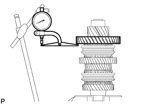
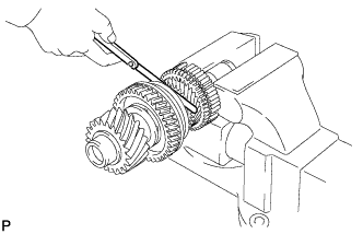
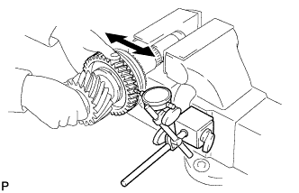
| 1. INSPECT 1ST DRIVEN GEAR THRUST CLEARANCE |
Using a dial indicator, measure the thrust clearance.
- Standard thrust clearance:
- 0.10 to 0.35 mm (0.0039 to 0.0138 in.)
- Maximum thrust clearance:
- 0.35 mm (0.0138 in.)
If the thrust clearance exceeds the maximum, replace the needle roller bearing or shaft.
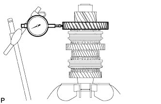
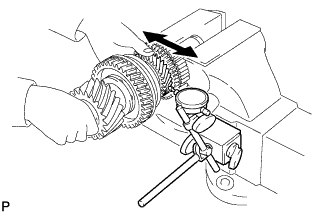
| 2. INSPECT 1ST DRIVEN GEAR RADIAL CLEARANCE |
Using a dial indicator, measure the radial clearance.
- Standard radial clearance:
- 0.015 to 0.068 mm (0.0006 to 0.0027 in.)
- Maximum clearance:
- 0.068 mm (0.0027 in.)
If the clearance exceeds the maximum, replace the 1st driven gear, needle roller bearing or shaft.
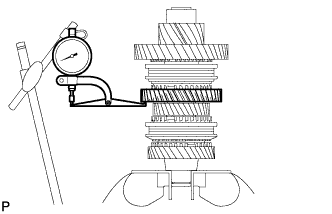
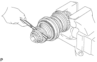
| 3. INSPECT 2ND DRIVEN GEAR THRUST CLEARANCE |
Using a dial indicator, measure the thrust clearance.
- Standard thrust clearance:
- 0.11 to 0.46 mm (0.0043 to 0.018 in.)
- Maximum thrust clearance:
- 0.46 mm (0.018 in.)
If the thrust clearance exceeds the maximum, replace the 2nd driven gear, needle roller bearing or shaft.
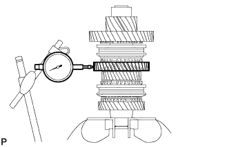
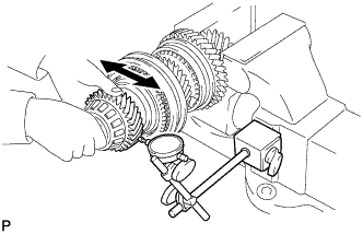
| 4. INSPECT 2ND DRIVEN GEAR RADIAL CLEARANCE |
Using a dial indicator, measure the radial clearance.
- Standard radial clearance:
- 0.015 to 0.048 mm (0.0006 to 0.0019 in.)
- Maximum radial clearance:
- 0.048 mm (0.0019 in.)
If the radial clearance exceeds the maximum, replace the 2nd driven gear, needle roller bearing or shaft.
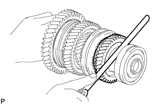
| 5. INSPECT 3RD DRIVEN GEAR THRUST CLEARANCE |
Using a feeler gauge, measure the thrust clearance.
- Standard thrust clearance:
- 0.11 to 0.54 mm (0.0043 to 0.0213 in.)
- Maximum thrust clearance:
- 0.54 mm (0.0213 in.)
If the thrust clearance exceeds the maximum, replace the 3rd driven gear, needle roller bearing or shaft.
| 6. INSPECT 3RD DRIVEN GEAR RADIAL CLEARANCE |
Using a dial indicator, measure the radial clearance.
- Standard radial clearance:
- 0.015 to 0.066 mm (0.0006 to 0.0026 in.)
- Maximum radial clearance:
- 0.066 mm (0.0026 in.)
If the radial clearance exceeds the maximum, replace the 3rd driven gear, needle roller bearing or shaft.
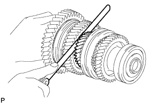
| 7. INSPECT 4TH DRIVEN GEAR THRUST CLEARANCE |
Using a feeler gauge, measure the thrust clearance.
- Standard thrust clearance:
- 0.10 to 0.65 mm (0.0039 to 0.0256 in.)
- Maximum thrust clearance:
- 0.65 mm (0.0256 in.)
If the thrust clearance exceeds the maximum, replace the 4th driven gear, needle roller bearing or shaft.
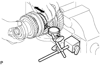
| 8. INSPECT 4TH DRIVEN GEAR RADIAL CLEARANCE |
Using a dial indicator, measure the radial clearance.
- Standard radial clearance:
- 0.015 to 0.066 mm (0.0006 to 0.0026 in.)
- Maximum radial clearance:
- 0.066 mm (0.0026 in.)
If the radial clearance exceeds the maximum, replace the 4th driven gear, needle roller bearing or shaft.
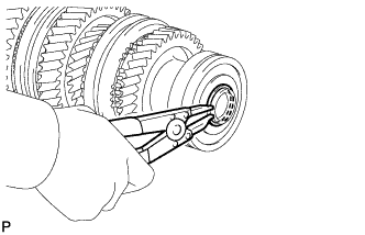
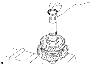
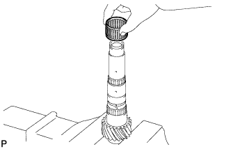
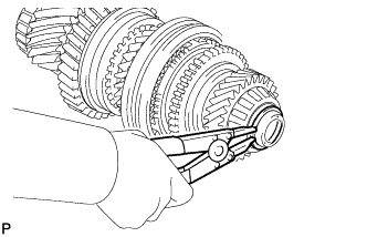
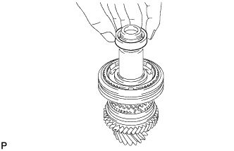
| 9. REMOVE OUTPUT SHAFT BEARING SHAFT SNAP RING |
Using a snap ring expander, remove the output shaft bearing shaft snap ring from the No. 1 output shaft.
| 10. REMOVE OUTPUT SHAFT FRONT BEARING |
Using SST and press, press out the output shaft front bearing from the No. 1 output shaft.
- Специальный инструмент (SST):
- 09201-31010
09950-00020
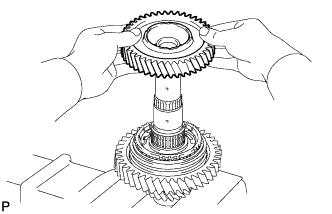
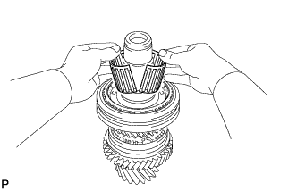
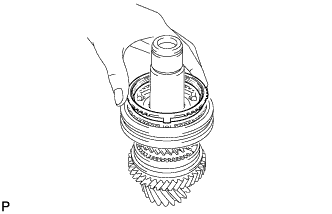
| 11. REMOVE 3RD DRIVEN GEAR |
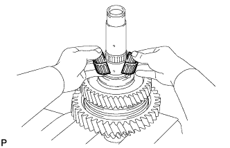
Remove the 3rd driven gear from the No. 1 output shaft.
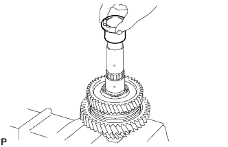
Remove the spacer from the No. 1 output shaft.
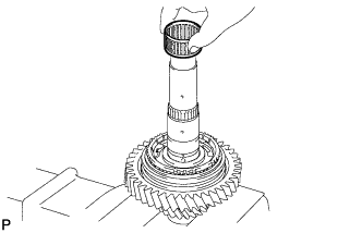
| 13. REMOVE NEEDLE ROLLER BEARING |
Remove the needle roller bearing from the No. 1 output shaft.
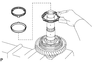
| 14. REMOVE 3RD DRIVEN GEAR SYNCHRONIZER RING SET |
Remove the synchronizer ring set from the No. 1 output shaft.
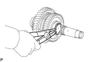
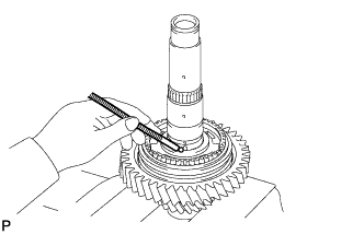
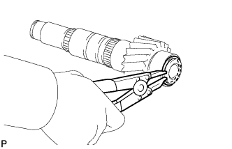
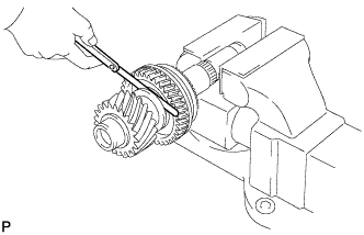
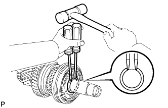
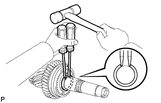
| 15. REMOVE SHAFT SNAP RING |
Using 2 screwdrivers and a hammer, tap out the shaft snap ring from the No. 1 output shaft.
| 16. REMOVE 4TH DRIVEN GEAR |
Using SST and a press, press out the hub sleeve No. 2, 4th gear synchronizer ring set and 4th driven gear from the No. 1 output shaft.
- Специальный инструмент (SST):
- 09950-00020
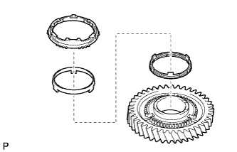
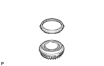
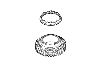
| 17. REMOVE 4TH DRIVEN GEAR SYNCHRONIZER RING SET |
Remove the 4th driven gear synchronizer ring set from the 4th driven gear.
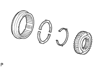
| 18. REMOVE NO. 2 TRANSMISSION CLUTCH HUB |
Remove the clutch hub, 3 keys, 3 balls and 3 key springs from the hub sleeve.
- ПРИМЕЧАНИЕ:
- Pay attention to prevent the balls and springs from scattering.
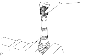
| 19. REMOVE NEEDLE ROLLER BEARING |
Remove the needle roller bearing from the No. 1 output shaft.
Remove the spacer from the No. 1 output shaft.
| 21. REMOVE OUTPUT SHAFT BEARING SHAFT SNAP RING |
Using a snap ring expander, remove the output shaft bearing shaft snap ring from the No. 1 output shaft.
| 22. REMOVE 2ND GEAR BEARING INNER RACE |
Remove the 2nd gear bearing inner race from the No. 1 output shaft.
| 23. REMOVE 2ND DRIVEN GEAR |
Remove the 2nd driven gear from the No. 1 output shaft.
| 24. REMOVE NEEDLE ROLLER BEARING |
Remove the needle roller bearing from the No. 1 output shaft.
| 25. REMOVE SYNCHROMESH SHIFTING KEY BALL |
Remove the synchromesh shifting key ball from the No. 1 output shaft.
| 26. REMOVE 2ND DRIVEN GEAR SYNCHRONIZER RING SET |
Remove the synchronizer ring set from the No. 1 output shaft.
| 27. REMOVE 1ST DRIVEN GEAR |
Using SST and a press, press out the No. 1 hub sleeve, 1st driven gear synchronizer ring set and 1st driven gear from the No. 1 output shaft.
- Специальный инструмент (SST):
- 09950-00020
| 28. REMOVE 1ST DRIVEN GEAR SYNCHRONIZER RING SET |
Remove the synchronizer ring set from the 1st driven gear.
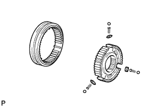
| 29. REMOVE NO. 1 TRANSMISSION CLUTCH HUB |
Remove the clutch hub, 3 keys, 3 balls and 3 key springs from the hub sleeve.
- ПРИМЕЧАНИЕ:
- Pay attention to prevent the balls and springs from scattering.
| 30. REMOVE NEEDLE ROLLER BEARING |
Remove the needle roller bearing from the No. 1 output shaft.
| 31. REMOVE OUTPUT SHAFT FRONT BEARING SHAFT SNAP RING |
Using a snap ring expander, remove the output shaft front bearing shaft snap ring from the No. 1 output shaft.
| 32. REMOVE OUTPUT SHAFT FRONT BEARING |
Using SST and a press, press out the output shaft front bearing from the No. 1 output shaft.
- Специальный инструмент (SST):
- 09201-31010
09950-00020
| 33. INSPECT 5TH DRIVEN GEAR THRUST CLEARANCE |
Using a feeler gauge, measure the thrust clearance.
- Standard thrust clearance:
- 0.10 to 0.55 mm (0.0039 to 0.0217 in.)
- Maximum thrust clearance:
- 0.55 mm (0.0217 in.)
If the thrust clearance exceeds the maximum, replace the 5th driven gear, needle roller bearing or shaft.
| 34. INSPECT 5TH DRIVEN GEAR RADIAL CLEARANCE |
Using a dial indicator, measure the radial clearance.
- Standard radial clearance:
- 0.015 to 0.066 mm (0.0006 to 0.0026 in.)
- Maximum radial clearance:
- 0.066 mm (0.0026 in.)
If the radial clearance exceeds the maximum, replace the 5th driven gear, needle roller bearing or shaft.
| 35. INSPECT 6TH DRIVEN GEAR THRUST CLEARANCE |
Using a feeler gauge, measure the thrust clearance.
- Standard thrust clearance:
- 0.10 to 0.55 mm (0.0039 to 0.0217 in.)
- Maximum thrust clearance:
- 0.55 mm (0.0217 in.)
If the thrust clearance exceeds the maximum, replace the 6th driven gear, needle roller bearing or shaft.
| 36. INSPECT 6TH DRIVEN GEAR RADIAL CLEARANCE |
Using a dial indicator, measure the radial clearance.
- Standard radial clearance:
- 0.015 to 0.066 mm (0.0006 to 0.0026 in.)
- Maximum radial clearance:
- 0.066 mm (0.0026 in.)
If the radial clearance exceeds the maximum, replace the 6th driven gear, needle roller bearing or shaft.
| 37. INSPECT REVERSE DRIVEN GEAR THRUST CLEARANCE |
Using a feeler gauge, measure the thrust clearance.
- Standard thrust clearance:
- 0.11 to 0.34 mm (0.0043 to 0.0134 in.)
- Maximum thrust clearance:
- 0.34 mm (0.0134 in.)
If the thrust clearance exceeds the maximum, replace the reverse driven gear, needle roller bearing or shaft.
| 38. INSPECT REVERSE DRIVEN GEAR RADIAL CLEARANCE |
Using a dial indicator, measure the gear radial clearance.
- Standard radial clearance:
- 0.015 to 0.068 mm (0.0006 to 0.0027 in.)
- Maximum radial clearance:
- 0.068 mm (0.0027 in.)
If the radial clearance exceeds the maximum, replace the reverse driven gear, needle roller bearing or shaft.
| 39. REMOVE NO. 2 OUTPUT SHAFT BEARING SNAP RING |
Using a snap ring expander, press out the No. 2 output shaft bearing snap ring from the No. 2 output shaft.
| 40. REMOVE NO. 2 OUTPUT SHAFT REAR BEARING |
Using SST and a press, remove the No. 2 output shaft rear bearing and 6th driven gear from the No. 2 output shaft.
- Специальный инструмент (SST):
- 09201-31010
09950-00020
| 41. REMOVE NEEDLE ROLLER BEARING |
Remove the needle roller bearing from the No. 2 output shaft.
Remove the spacer from the No. 2 output shaft.
| 43. REMOVE 6TH GEAR SYNCHRONIZER RING |
Remove the 6th gear synchronizer ring from the No. 2 output shaft.
| 44. REMOVE SHAFT SNAP RING |
Using 2 screwdrivers and a hammer, tap out the shaft snap ring from the No. 2 output shaft.
| 45. REMOVE 5TH DRIVEN GEAR |
Using SST and a press, press out the No. 3 hub sleeve, 5th synchronizer ring and 5th driven gear from the No. 2 output shaft.
- Специальный инструмент (SST):
- 09950-00020
| 46. REMOVE 5TH DRIVEN GEAR SYNCHRONIZER RING |
Remove the 5th driven gear synchronizer ring from the 5th driven gear.
| 47. REMOVE NO. 3 TRANSMISSION CLUTCH HUB |
Remove the No. 3 clutch hub, 3 keys, 3 balls and 3 key springs from the hub sleeve.
- ПРИМЕЧАНИЕ:
- Pay attention to prevent the balls and springs from scattering.
| 48. REMOVE SHAFT SNAP RING |
Using 2 screwdrivers and a hammer, remove the shaft snap ring from the No. 2 output shaft.
| 49. REMOVE REVERSE DRIVEN GEAR |
Using SST and a press, press out the No. 4 hub sleeve, reverse gear synchronizer ring set and reverse driven gear from the No. 2 output shaft.
- Специальный инструмент (SST):
- 09950-00020
| 50. REMOVE REVERSE DRIVEN GEAR SYNCHRONIZER RING |
Remove the reverse driven gear synchronizer ring from the reverse gear.
| 51. REMOVE NO. 4 TRANSMISSION CLUTCH HUB |
Remove the No. 4 transmission clutch hub, synchromesh shifting key spring and 2 synchromesh shifting keys from the transmission hub sleeve.
| 52. REMOVE NEEDLE ROLLER BEARING |
Remove the needle roller bearing from the No. 2 output shaft.
| 53. REMOVE NO. 2 OUTPUT SHAFT FRONT BEARING |
Using SST and a press, press out the No. 2 output shaft front bearing from the No. 2 output shaft.
- Специальный инструмент (SST):
- 09201-31010
09950-00020