Intake Air Control System System Diagram
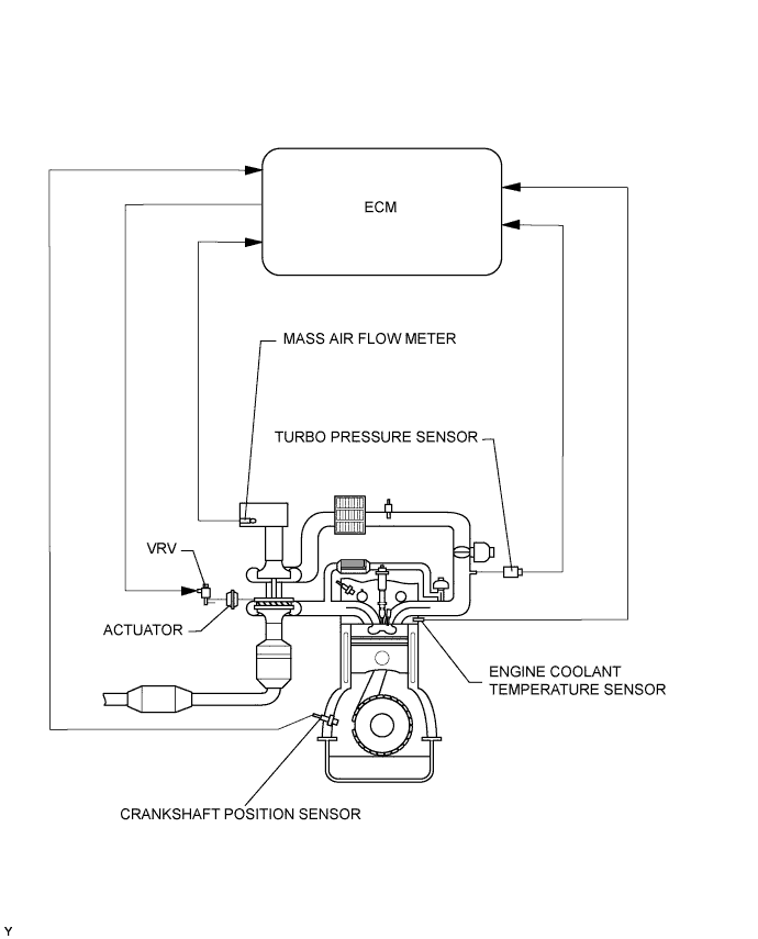
TURBOCHARGER SYSTEM ILLUSTRATION
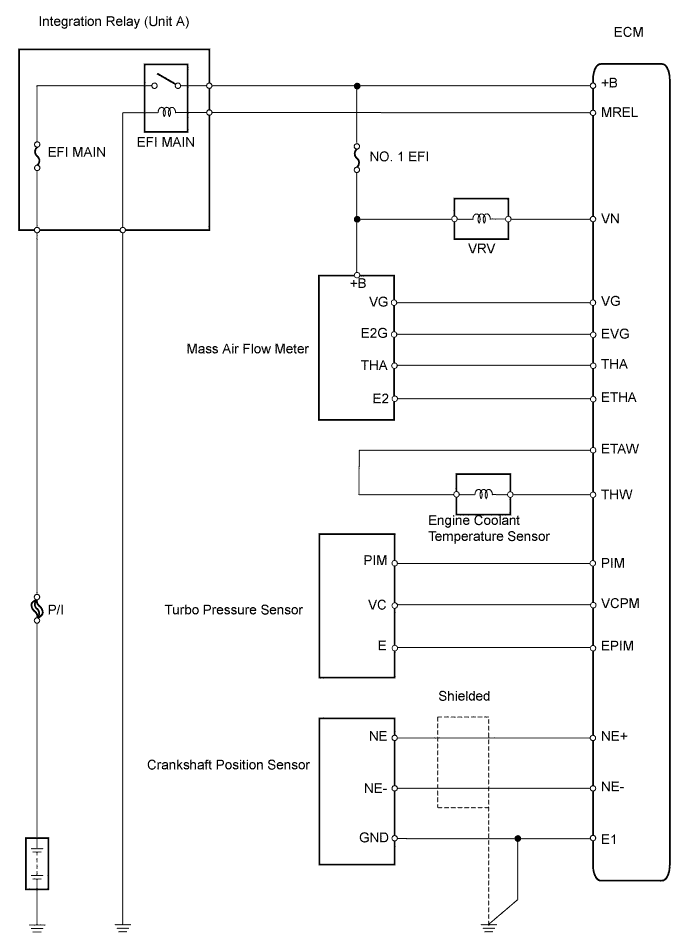
TURBOCHARGER SYSTEM WIRING DIAGRAM
Intake Air Control System -- System Diagram |
| TURBOCHARGER SYSTEM ILLUSTRATION |
- The ECM calculates an optimal turbo pressure in accordance with the driving conditions (engine speed, injection volume, atmospheric pressure, and water temperature). It controls the variable nozzle so that the turbo pressure detected by the turbo pressure sensor matches the calculated turbo pressure.
- The turbo pressure (intake manifold pressure) is controlled by the variable nozzle vane located in the turbine area. This nozzle is actuated by the actuator that is directly connected to it. This actuator is actuated by the vacuum pressure that is regulated by the VRV (Vacuum Regulating Valve) in accordance with the signals from the ECM.
| TURBOCHARGER SYSTEM WIRING DIAGRAM |