Fuel Supply Pump -- Installation |
| 1. INSTALL FUEL SUPPLY PUMP ASSEMBLY |
Install a new O-ring to the supply pump.
Install the supply pump drive coupling.
- ПРИМЕЧАНИЕ:
- When reusing the coupling, it must be installed in the same orientation (top/bottom, front/back) as when it was removed,
- УКАЗАНИЕ:
- Line up the coupling with the groove in the camshaft end.
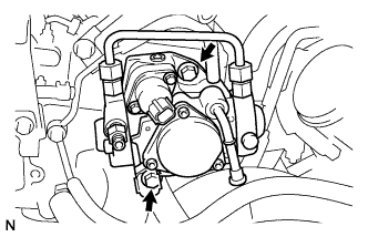 |
Install the supply pump with the 2 bolts.
- Момент затяжки:
- 20.5 Н*м{209 кгс*см, 15 фунт-сила-футов}
- ПРИМЕЧАНИЕ:
- Apply engine oil on the O-ring of the supply pump.
- УКАЗАНИЕ:
- Line up the end of the supply pump drive shaft with the supply pump drive coupling.
Connect the suction control valve connector.
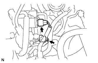 |
Connect the fuel temperature sensor connector.
| 2. INSTALL FUEL INLET PIPE SUB-ASSEMBLY |
- ПРИМЕЧАНИЕ:
- In a case where the supply pump is replaced, the fuel inlet pipe must also be replaced.
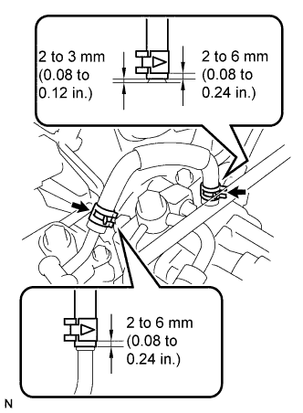
Temporarily install the fuel inlet pipe with the 2 clamps and nut.
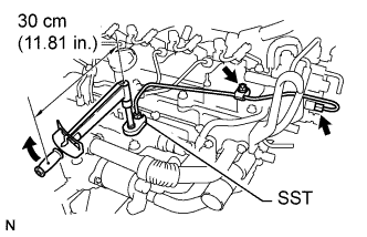 |
Using SST, first tighten the nut at the common rail end of the fuel inlet pipe.
- Специальный инструмент (SST):
- 09023-38401
- Момент затяжки:
- 27 Н*м{275 кгс*см, 20 фунт-сила-футов}
- УКАЗАНИЕ:
- Use of the proper SST is required to ensure that the correct torque is applied to the inlet pipe nut.
- Use a torque wrench with a fulcrum length of 30 cm (11.81 in.).
- Make sure that the pipe is not deformed or twisted during installation.
- If the pipe is deformed or twisted, or if it cannot be installed properly, replace the pipe with a new pipe.
Using SST, tighten the nut at the supply pump end of the fuel inlet pipe.
- Специальный инструмент (SST):
- 09023-38401
- Момент затяжки:
- 27 Н*м{275 кгс*см, 20 фунт-сила-футов}
- УКАЗАНИЕ:
- Use of the proper SST is required to ensure that the correct torque is applied to the inlet pipe nut.
- Use a torque wrench with a fulcrum length of 30 cm (11.81 in.).
- Make sure that the pipe is not deformed or twisted during installation.
- If the pipe is deformed or twisted, or if it cannot be installed properly, replace the pipe with a new pipe.
Tighten the fuel inlet pipe clamp nut.
- Момент затяжки:
- 5.0 Н*м{51 кгс*см, 44 фунт-сила-дюймов}
| 3. INSTALL FUEL TUBE SUB-ASSEMBLY |
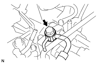
Install a new gasket and the fuel tube with the union bolt.
- Момент затяжки:
- 23 Н*м{235 кгс*см, 17 фунт-сила-футов}
 |
Turn the retainer in the direction indicated by the arrow until the retainer stops.
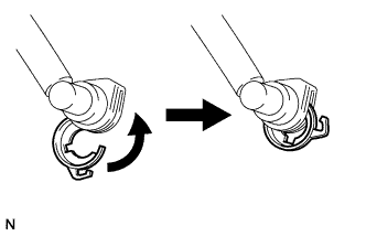 |
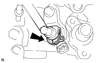
Insert the fuel tube connector into the injector.
 |
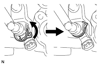
Turn the retainer in the direction indicated by the arrow until it makes a "click" sound.
- ПРИМЕЧАНИЕ:
- If the fuel tube connector is not inserted to the correct position in the injector, the retainer cannot be turned farther in the direction of the arrow.
 |
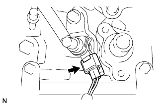
Connect the exhaust fuel addition injector connector.
 |
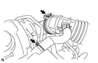
| 4. INSTALL NO. 1 FUEL HOSE |
Using pliers, grip the claws of the 2 clips and slide the 2 clips to install the No. 1 fuel hose.
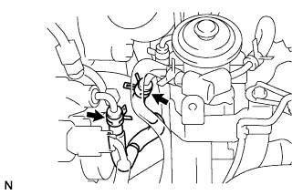 |
| 5. INSTALL NO. 3 FUEL HOSE |
Using pliers, grip the claws of the 2 clips and slide the 2 clips to install the No. 3 fuel hose as shown in the illustration.
 |
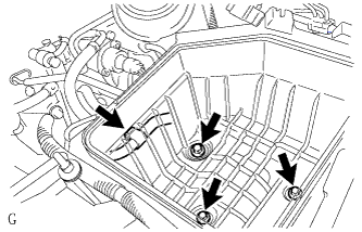
| 6. INSTALL AIR CLEANER ASSEMBLY |
Install the cleaner case with the 3 bolts and connect the wire harness clamp.
- Момент затяжки:
- 5.0 Н*м{51 кгс*см, 44 фунт-сила-дюймов}
 |
Install the air filter element.
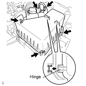
Using pliers, grip the claws of the clip to install the air cleaner cap.
 |
Using pliers, grip the claws of the clip and slide the clip to connect the PCV hose.
Insert the hinge parts of the air cleaner cap into the air cleaner case, and then hang the 3 hook clamps.
 |
Connect the mass air flow meter connector.
Attach the wire harness clamp.
| 7. CONNECT CABLE TO NEGATIVE BATTERY TERMINAL |
| 8. BLEED AIR FROM FUEL SYSTEM |
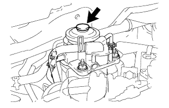
Using the hand pump indicated by the arrows in the illustration, bleed the fuel system. Continue pumping until pumping becomes difficult.
 |
| 9. CHECK FOR FUEL LEAKS |
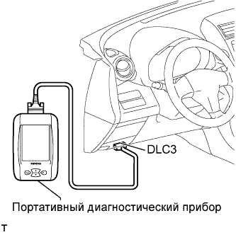
Perform the ACTIVE TEST.
Connect the intelligent tester to the DLC3.
Turn the ignition switch on (IG).
Turn the intelligent tester ON.
Enter the following menus: Powertrain / Engine / Active Test.
Perform the Active Test.
Intelligent Tester Display Test Details Control Range Diagnostic Notes Test the Fuel Leak Pressurizing common rail internal fuel pressure, and checking for fuel leaks Stop/Start - Fuel pressure inside common rail pressurized to specified value and engine speed increased to 2,000 rpm when Start is selected
- Above conditions to be maintained while test is Start
- Fuel pressure inside common rail pressurized to specified value and engine speed increased to 2,000 rpm when Start is selected
 |
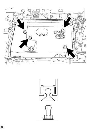
| 10. INSTALL NO. 1 ENGINE COVER |
Attach the 4 clips to install the engine cover.
 |