Cylinder Head -- Installation |
| 1. INSTALL CYLINDER HEAD GASKET |
Place a new gasket on the cylinder block surface with the Lot No. stamp facing upward.
- ПРИМЕЧАНИЕ:
- Remove any oil from contact surface.
- Be careful of the installation direction.
 |
| 2. INSTALL CYLINDER HEAD SUB-ASSEMBLY |
Place the cylinder head on the head gasket.
- ПРИМЕЧАНИЕ:
- Place the cylinder head gently in order to avoid damaging the gasket.
Install the cylinder head bolts.
- ПРИМЕЧАНИЕ:
- The cylinder head bolts are tightened in 2 successive steps.
Apply a light coat of engine oil to the threads and under the heads of the cylinder head set bolts.
Using several steps, uniformly install and tighten the 10 cylinder head set bolts and plate washers with a 10 mm bi-hexagon wrench in the order shown in the illustration.
- Момент затяжки:
- 78.5 Н*м{800 кгс*см, 58 фунт-сила-футов}

Mark the front of the cylinder head bolts with paint.
 |
Retighten the cylinder head bolts by 90°as shown in the illustration.
Check that the paint mark is now at a 90°angle to the front.
| 3. INSTALL CAMSHAFT TIMING GEAR ASSEMBLY |
Put the camshaft timing gear and camshaft together with the straight pin and key groove misaligned, as shown in the illustration.
 |
Turn the camshaft timing gear as shown in the illustration while pushing it gently against the camshaft. Push further at the position where the pin fits into the groove.
- ПРИМЕЧАНИЕ:
- Be sure not to turn the camshaft timing gear to the retard angle side (the right angle).
Check that there is no clearance between the gear fringe and camshaft.
Tighten the flange bolt with the camshaft timing gear fixed in place.
- Момент затяжки:
- 54 Н*м{551 кгс*см, 40 фунт-сила-футов}
Check that the camshaft timing gear can move to the retard angle side (the right direction) and is locked in the most retarded position.
| 4. INSTALL NO. 2 CAMSHAFT TIMING SPROCKET |
Clamp the camshaft in a vise, then install the camshaft timing sprocket with the bolt.
- Момент затяжки:
- 54 Н*м{551 кгс*см, 40 фунт-сила-футов}
- ПРИМЕЧАНИЕ:
- Do not damage the camshaft.
 |
| 5. INSTALL CAMSHAFT |
Apply a light coat of engine oil to the journal portion of the camshaft.
Place the 2 camshafts on the cylinder head with the No. 1 cam lobes facing the directions shown in the illustration.
 |
Examine the front marks and numbers, and check that the order is as shown in the illustration. Then install the bearing caps onto the cylinder head.
 |
Apply a light coat of engine oil to the threads and under the heads of the bearing cap bolts.
Using several steps, uniformly tighten the 20 bearing cap bolts in the sequence shown in the illustration.
- Момент затяжки:
- 29.5 Н*м{301 кгс*см, 22 фунт-сила-футов} for No. 1 and No. 2 bearing cap
- 9.0 Н*м{92 кгс*см, 80 фунт-сила-дюймов} for No. 3 bearing cap
- ПРИМЕЧАНИЕ:
- Tighten the bolts after deciding the position in the thrust direction of the camshaft by the No. 1 and No. 2 bearing caps.
- Install the camshaft with the timing mark of the camshaft timing gear on top.
 |
| 6. INSTALL NO. 1 CHAIN VIBRATION DAMPER |
Install the chain vibration damper with the 2 bolts.
- Момент затяжки:
- 9.0 Н*м{92 кгс*см, 80 фунт-сила-дюймов}
 |
| 7. INSTALL CHAIN SUB-ASSEMBLY |
Set the No. 1 cylinder to TDC/compression.
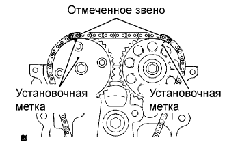
Turn the camshafts with a wrench (using the hexagonal lobe) to align the timing marks of the camshaft timing gear with each timing mark located on the No. 1 and No. 2 bearing caps as shown in the illustration.
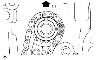
Using the crankshaft pulley bolt, turn the crankshaft to position the key on the crankshaft upward.
 |
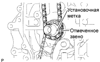
Install the chain onto the crankshaft timing sprocket with the gold or orange mark link aligned with the timing mark on the crankshaft.
 |
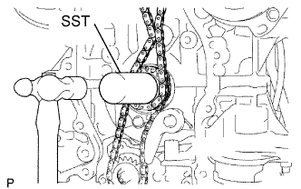
Using SST and a hammer, tap in the crankshaft timing sprocket.
- Специальный инструмент (SST):
- 09309-37010
 |
Align the gold or yellow links with each timing mark located on the camshaft timing gear and sprocket, then install the chain.
 |
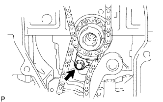
| 8. INSTALL CHAIN TENSIONER SLIPPER |
Install the chain tensioner slipper with the bolt.
- Момент затяжки:
- 19 Н*м{194 кгс*см, 14 фунт-сила-футов}
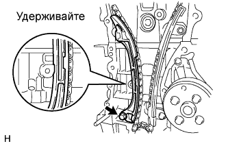 |
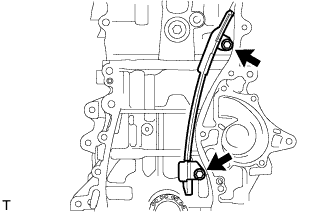
| 9. INSTALL TIMING CHAIN GUIDE |
Install the timing chain guide with the bolt.
- Момент затяжки:
- 9.0 Н*м{92 кгс*см, 80 фунт-сила-дюймов}
 |
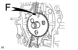
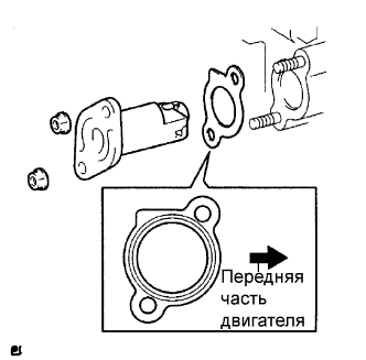
| 10. INSTALL NO. 1 CRANKSHAFT POSITION SENSOR PLATE |
Install the sensor plate with the "F" mark facing forward.
 |
| 11. INSTALL TIMING CHAIN COVER SUB-ASSEMBLY |
Remove any old packing material and be careful not to drop any oil on the contact surfaces of the timing chain cover, cylinder head and cylinder block.
Apply seal packing (Diameter 4.0 to 4.5 mm (0.157 to 0.177 in.)) as shown in the illustration.
- Seal packing:
- Toyota Genuine Seal Packing Black, Three Bond 1207B or Equivalent
- ПРИМЕЧАНИЕ:
- Remove any oil from the contact surface.
- Install the chain cover within 3 minutes of applying seal packing.
- Do not add engine oil for at least 2 hours after installing the chain cover.
 |
Apply a continuous bead of seal packing as shown in the illustration.
- Seal packing:
- Toyota Genuine Seal Packing Black, Three Bond 1207B or Equivalent
- ПРИМЕЧАНИЕ:
- Remove any oil from the contact surface.
- Install the chain cover within 3 minutes of applying seal packing.
- Do not add engine oil for at least 2 hours after installing the chain cover.

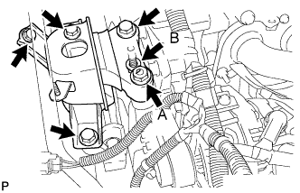
Install the timing chain cover with the 12 bolts and 2 nuts.
- Момент затяжки:
- 9.0 Н*м{92 кгс*см, 80 фунт-сила-дюймов} for bolt A
- 25 Н*м{255 кгс*см, 18 фунт-сила-футов} for bolt B
- 55 Н*м{561 кгс*см, 41 фунт-сила-футов} for bolt C
- 11 Н*м{112 кгс*см, 8 фунт-сила-футов} for nut
- УКАЗАНИЕ:
- Bolt length:
Bolt A 30 mm (1.18 in.) length for 10 mm head Bolt B 30 mm (1.18 in.) length for 12 mm head Bolt C 40 mm (1.57 in.) length for 14 mm head
 |
Using an E10 "torx" socket, install the stud bolt for the V-ribbed belt tensioner.
- Момент затяжки:
- 21.5 Н*м{219 кгс*см, 16 фунт-сила-футов}
 |
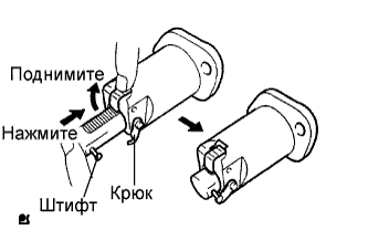
| 12. INSTALL NO. 1 CHAIN TENSIONER ASSEMBLY |
Release the ratchet pawl, then fully push in the plunger and hook the hook to the pin so that the plunger is in the position shown in the illustration.
 |
Install a new gasket and the chain tensioner with the 2 nuts.
- Момент затяжки:
- 9.0 Н*м{92 кгс*см, 80 фунт-сила-дюймов}
- ПРИМЕЧАНИЕ:
- When installing the chain tensioner, set the hook again if the hook releases the plunger.
 |
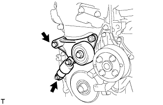
| 13. INSTALL V-RIBBED BELT TENSIONER ASSEMBLY |
Install the V-ribbed belt tensioner with the bolt and nut.
- Момент затяжки:
- 59.5 Н*м{607 кгс*см, 44 фунт-сила-футов}
- ПРИМЕЧАНИЕ:
- Do not lift the engine more than necessary.
 |
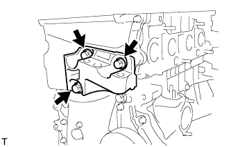
| 14. INSTALL ENGINE MOUNTING BRACKET RH |
Install the engine mounting bracket RH with the 3 bolts.
- Момент затяжки:
- 55 Н*м{561 кгс*см, 41 фунт-сила-футов}
 |
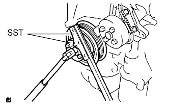
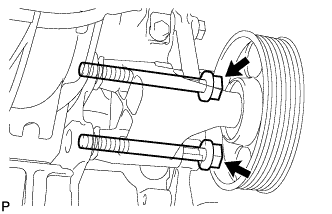
| 15. INSTALL CRANKSHAFT PULLEY |
Using SST, fix the pulley in place and tighten the bolt.
- Специальный инструмент (SST):
- 09213-54015(91651-60855)
09330-00021
- Момент затяжки:
- 180 Н*м{1,835 кгс*см, 133 фунт-сила-футов}
 |
Turn the crankshaft counterclockwise, then disconnect the plunger knock pin from the hook.
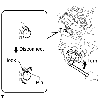 |
Turn the crankshaft clockwise, then check that the plunger is extended.
 |
| 16. INSTALL OIL PAN SUB-ASSEMBLY |
Remove any old packing material and be careful not to drop any oil on the contact surfaces of the cylinder block and oil pan.
Apply a continuous bead of seal packing (Diameter 3.0 to 4.0 mm (0.118 to 0.157 in.)) as shown in the illustration.
- Seal packing:
- Toyota Genuine Seal Packing Black, Three Bond 1207B or Equivalent
- ПРИМЕЧАНИЕ:
- Remove any oil from the contact surface.
- Install the oil pan within 3 minutes of applying seal packing.
- Do not add engine oil for at least 2 hours after installing the oil pan.
 |
Install the oil pan to the cylinder block.
Uniformly tighten the 12 bolts and 2 nuts in the sequence shown in the illustration.
- Момент затяжки:
- 9.0 Н*м{92 кгс*см, 80 фунт-сила-дюймов}
 |
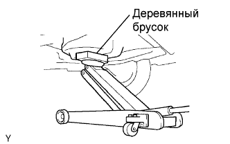
Place a transmission jack underneath the engine, then put a wooden block on the jack.
 |
Remove the chain block and sling device.
Remove the No. 1 and No. 2 engine hangers.
| 17. INSTALL CRANKSHAFT POSITION SENSOR |
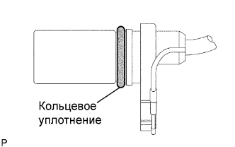 |
- ПРИМЕЧАНИЕ:
- Make sure that the O-ring is not cracked or jammed when installing it.
Apply a light coat of engine oil to the O-ring of the sensor.
Install the sensor with the bolt.
- Момент затяжки:
- 9.0 Н*м{90 кгс*см, 80 фунт-сила-дюймов}
 |
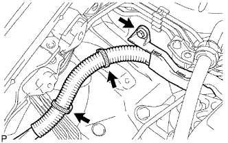
Install the wire harness clamp.
Install the connector clamp.
Connect the sensor connector.
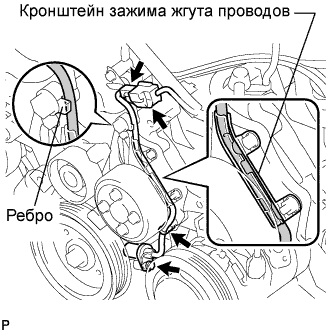
Confirm that the wire harness of the sensor is secured to the wire harness clamp bracket through the back of the rib of the timing chain cover.
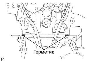
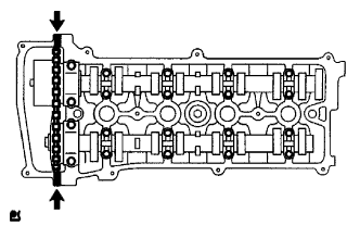
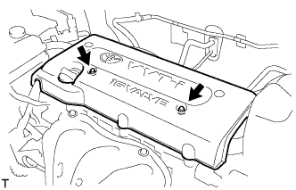
| 18. INSTALL CYLINDER HEAD COVER SUB-ASSEMBLY |
Remove any old packing material from the contact surface.
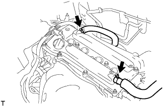
Apply seal packing to the 2 locations shown in the illustration.
- Seal packing:
- Toyota Genuine Seal Packing Black, Three Bond 1207B or Equivalent
- ПРИМЕЧАНИЕ:
- Remove any oil from the contact surface.
- Install the oil pan within 3 minutes of applying seal packing.
- Do not add engine oil for at least 2 hours after installing the oil pan.
 |
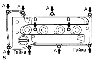
Install the cylinder head cover with the 8 bolts and 2 nuts.
- Момент затяжки:
- 11 Н*м{112 кгс*см, 8 фунт-сила-футов} for bolt A
- 14 Н*м{143 кгс*см, 10 фунт-сила-футов} for bolt B
- 11 Н*м{112 кгс*см, 8 фунт-сила-футов} for nut
 |
Install the 2 engine wires with the 2 bolts.
- Момент затяжки:
- 8.4 Н*м{86 кгс*см, 74 фунт-сила-дюймов}
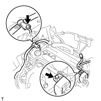 |
Connect the clamp of the engine wire (labeled B).
Connect the 2 ventilation hoses to the cylinder head cover.
 |
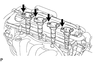
| 19. INSTALL IGNITION COIL ASSEMBLY |
Install the 4 ignition coils with the 4 bolts.
- Момент затяжки:
- 9.0 Н*м{92 кгс*см, 80 фунт-сила-дюймов}
 |
Connect the 4 ignition coil connectors.
| 20. INSTALL IDLER PULLEY |
Install the idler bracket with the 2 bolts.
- Момент затяжки:
- 60 Н*м{612 кгс*см, 44 фунт-сила-футов}
 |
| 21. INSTALL ENGINE MOUNTING INSULATOR RH |
Install the engine mounting insulator RH with the 4 bolts and 2 nuts.
- Момент затяжки:
- 95 Н*м{969 кгс*см, 70 фунт-сила-футов} for bolt
- 95 Н*м{969 кгс*см, 70 фунт-сила-футов} for nut A
- 52 Н*м{530 кгс*см, 38 фунт-сила-футов} for nut B
 |
Connect the 2 clamps of the engine wire.
 |
Install the wire harness protector with the bolt.
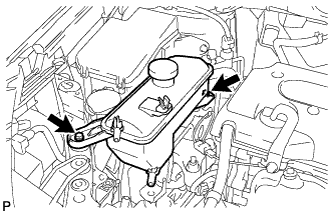
| 22. INSTALL RADIATOR RESERVOIR |
Install the reservoir with the 2 bolts.
- Момент затяжки:
- 5.0 Н*м{51 кгс*см, 44 фунт-сила-дюймов}
 |
| 23. INSTALL GENERATOR ASSEMBLY |
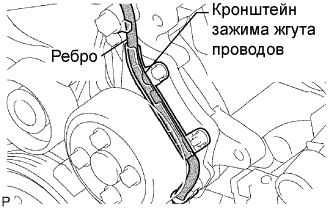
Confirm that the wire harness of the crankshaft position sensor is secured to the wire harness clamp bracket through the back of the rib of the timing chain cover.
 |
Install the generator with the 2 bolts.
- Момент затяжки:
- 21 Н*м{215 кгс*см, 16 фунт-сила-футов}for bolt A
- 52 Н*м{530 кгс*см, 38 фунт-сила-футов}for bolt B
 |
Install the wire harness clamp.
 |
Install the wire harness clamp bracket with the bolt.
- Момент затяжки:
- 8.4 Н*м{85 кгс*см, 74 фунт-сила-дюймов}
Connect the generator wire with the nut.
- Момент затяжки:
- 9.8 Н*м{100 кгс*см, 7 фунт-сила-футов}
Install the terminal cap.
Connect the generator connector.
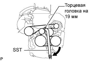
| 24. INSTALL FAN AND GENERATOR V BELT |
Using SST and 19 mm socket wrench, loosen the V-ribbed belt tensioner arm clockwise, then install the fan and generator V belt.
- Специальный инструмент (SST):
- 09216-42010
- ПРИМЕЧАНИЕ:
- Be sure to connect SST and the tools so that they are in line during use.
- When retracting the tensioner, turn it clockwise slowly for 3 seconds or more. Do not apply force rapidly.
- After the tensioner is fully retracted, do not apply force any more than necessary.
 |
| 25. INSTALL FRONT SUSPENSION MEMBER REINFORCEMENT RH |
Install the reinforcement RH with the 4 bolts.
- Момент затяжки:
- 96 Н*м{989 кгс*см, 71 фунт-сила-футов}
| 26. CONNECT ENGINE WIRE |
Connect the ground cable with the bolt.
- Момент затяжки:
- 8.4 Н*м{86 кгс*см, 74 фунт-сила-дюймов}
 |
Connect the camshaft position sensor connector.
Connect the engine coolant temperature sensor connector.
Connect the engine oil pressure switch connector.
Connect the radio setting condenser connector.
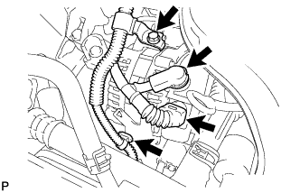
Connect the heater water inlet hose.
| 27. CONNECT NO. 1 RADIATOR HOSE |
Connect the hose to the cylinder head.
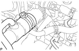 |
| 28. INSTALL CAMSHAFT TIMING OIL CONTROL VALVE ASSEMBLY |
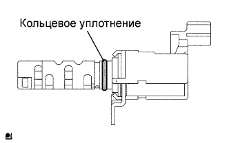
Apply a light coat of engine oil to the O-ring of the oil control valve.
 |
Install the oil control valve with the bolt.
- Момент затяжки:
- 9.0 Н*м{92 кгс*см, 80 фунт-сила-дюймов}
- ПРИМЕЧАНИЕ:
- Make sure that the O-ring is not cracked or jammed.
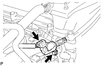 |
Connect the oil control valve connector.
| 29. INSTALL EXHAUST MANIFOLD CONVERTER SUB-ASSEMBLY |
Install a new gasket onto the cylinder head.
Temporarily tighten the exhaust manifold converter with the 5 nuts.
Tighten the 5 nuts in the sequence shown in the illustration.
- Момент затяжки:
- 37 Н*м{377 кгс*см, 27 фунт-сила-футов}
 |
| 30. INSTALL NO. 1 EXHAUST MANIFOLD HEAT INSULATOR |
Install the exhaust manifold heat insulator with the 4 bolts.
- Момент затяжки:
- 12 Н*м{122 кгс*см, 9 фунт-сила-футов}
 |
Connect the air-fuel ratio sensor connector.
 |
| 31. INSTALL NO. 2 MANIFOLD STAY |
Install the stay with the bolt and nut.
- Момент затяжки:
- 44 Н*м{449 кгс*см, 32 фунт-сила-футов}
 |
| 32. INSTALL MANIFOLD STAY |
Install the stay with the bolt and nut.
- Момент затяжки:
- 44 Н*м{449 кгс*см, 32 фунт-сила-футов}
 |
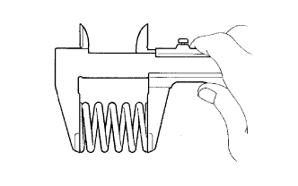
| 33. INSTALL FRONT EXHAUST PIPE |
Using a vernier caliper, measure the free length of the compression spring.
- Minimum length:
- 41.5 mm (1.634 in.)
 |
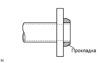
Install a new gasket by hand so that its surface is flush with the exhaust manifold.
- ПРИМЕЧАНИЕ:
- Make sure the gasket is facing the correct direction.
- Do not reuse the removed gasket.
- Do not push in the gasket while installing the front exhaust pipe.
 |
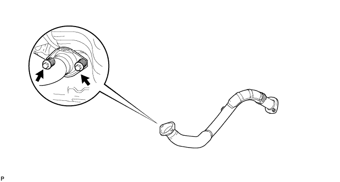
Install the front exhaust pipe with the 2 compression springs and 2 bolts.
- Момент затяжки:
- 43 Н*м{438 кгс*см, 32 фунт-сила-футов}
| 34. INSTALL OIL DIPSTICK GUIDE |
Apply a light coat of engine oil to a new O-ring and install it onto the guide.
Install the guide with the bolt.
- Момент затяжки:
- 9.0 Н*м{92 кгс*см, 80 фунт-сила-дюймов}
 |
| 35. INSTALL OIL DIPSTICK |
| 36. INSTALL INTAKE MANIFOLD INSULATOR |
Install the intake manifold insulator onto the cylinder block.
 |
| 37. INSTALL INTAKE MANIFOLD |
Install a new gasket into the intake manifold.
 |
Install the intake manifold with the 5 bolts and 2 nuts.
- Момент затяжки:
- 30 Н*м{305 кгс*см, 22 фунт-сила-футов}
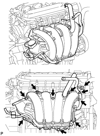 |
Fit the union to check valve hose into the vacuum hose clamp.
Install the wire harness clamp.
Connect the camshaft timing oil control valve connector.
Connect the union to check valve hose to the brake booster.
| 38. INSTALL FUEL DELIVERY PIPE SUB-ASSEMBLY |
Install 4 new insulators into the cylinder head.
 |
Install the 2 delivery pipe spacers onto the cylinder head.
Install the fuel delivery pipe together with the 4 fuel injectors, then temporarily tighten the 2 bolts.
- ПРИМЕЧАНИЕ:
- Be careful not to drop the fuel injectors when installing the fuel delivery pipe.
 |
Check that the fuel injector rotates smoothly.
If the fuel injector does not rotate, replace the O-ring.
Tighten the 2 bolts to the specified torque.
- Момент затяжки:
- 20 Н*м{205 кгс*см, 15 фунт-сила-футов}
 |
Connect the 4 fuel injector connectors.
 |
Install the 2 wire harness clamps.
| 39. INSTALL THROTTLE BODY |
Install a new gasket onto the intake manifold.
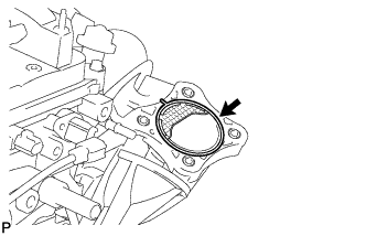 |
Install the throttle body and fuel pipe clamp with the 4 bolts.
- Момент затяжки:
- 30 Н*м{305 кгс*см, 22 фунт-сила-футов}
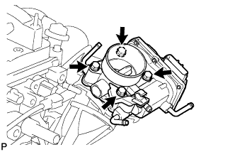 |
Connect the fuel tube into the clamp.
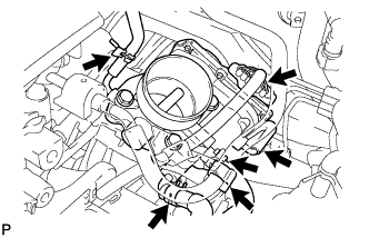 |
Connect the wire harness clamp.
Connect the throttle position sensor and control motor connector.
Connect the No. 1 throttle body hose to the throttle body.
Connect the No. 2 water by-pass hose to the throttle body.
Connect the water by-pass hose to the throttle body.
Connect the purge line hose to the throttle body.
| 40. INSTALL AIR CLEANER CAP |
Install the air cleaner filter element onto the air cleaner case.
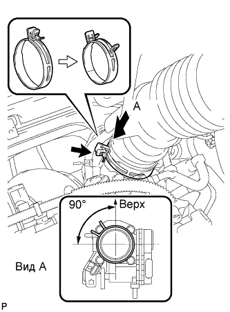
Insert the hinge part of the air cleaner cap into the air cleaner case, then hang the 2 hook clamps.
 |
Align the matchmarks of the No. 1 air cleaner hose and throttle body, and then connect the air cleaner hose No. 1 to the throttle body and unfasten the No. 1 air cleaner hose clamp.
- ПРИМЕЧАНИЕ:
- Make sure that the hose clamp is at the correct angle.
 |
Connect the purge line hose to the clamp.
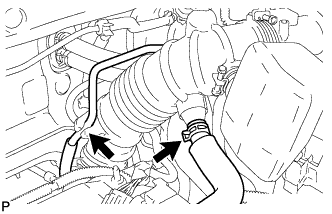 |
Connect the No. 2 ventilation hose to the air cleaner hose.
Install the 4 wire harness clamps.
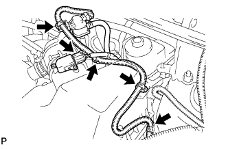 |
Connect the mass air flow meter connector.
| 41. ADD ENGINE OIL |
Clean and install the oil drain plug with a new gasket.
- Момент затяжки:
- 40 Н*м{408 кгс*см, 30 фунт-сила-футов}
Add new oil.
- Standard capacity:
Item Standard Condition Drain and refill with oil filter change 4.3 liters (4.5 US qts, 3.8 Imp. qts) Drain and refill without oil filter change 4.1 liters (4.3 US qts, 3.6 Imp. qts) Dry fill 5.0 liters (5.3 US qts, 4.4 Imp. qts)
Install the oil filler cap.
| 42. CONNECT CABLE TO NEGATIVE BATTERY TERMINAL |
| 43. CHECK FOR FUEL LEAKS |
| 44. ADD ENGINE COOLANT |
Tighten the radiator drain cock plug by hand.
Tighten the cylinder block drain cock plug.
- Момент затяжки:
- 12.7 Н*м{130 кгс*см, 10 фунт-сила-футов}
Add TOYOTA Super Long Life Coolant (SLLC) to the radiator reservoir filler opening.
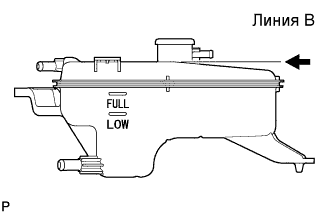
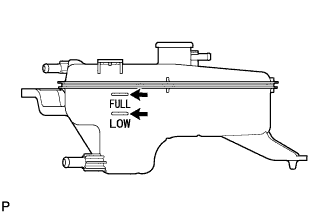
Continue adding TOYOTA SLLC until it is filled to the B line at the base of the reservoir's filler neck.
- УКАЗАНИЕ:
- The B line is the lower edge of the inner wall of the filler neck.
- Standard capacity:
Item Specified Condition A/T 6.5 liters (6.9 US qts, 5.7 Imp. qts) M/T 6.6 liters (7.0 US qts, 5.9 Imp. qts)
- УКАЗАНИЕ:
- TOYOTA vehicles are filled with TOYOTA SLLC at the factory. In order to avoid damage to the engine cooling system and other technical problems, only use TOYOTA SLLC or similar high quality ethylene glycol based non-silicate, non-amine, non-nitrite, non-borate coolant with long-life hybrid organic acid technology (coolant with long-life hybrid organic acid technology consists of a combination of low phosphates and organic acids).
- ПРИМЕЧАНИЕ:
- Never use water as a substitute for engine coolant.
 |
Press the No. 1 and No. 2 radiator hoses several times by hand, and then check the level of the coolant. If the coolant level drops below the B line, add TOYOTA SLLC to the B line.
Install the radiator reservoir cap.
Start the engine and warm it up until the cooling fan operates.
Set the air conditioning as follows while warming up the engine.
Item Specified Condition Manual Air Conditioning System Fan speed: Any setting except OFF
Temperature: Toward WARM
Air conditioning switch: OFFAutomatic Air Conditioning System Temperature: Toward MAX
Air conditioning switch: OFFMaintain the engine speed at 2,000 to 2,500 rpm and warm up the engine until the cooling fan operates.
- ПРИМЕЧАНИЕ:
- Make sure that the radiator reservoir still has some coolant in it.
- Pay attention to the needle of the water temperature meter. Make sure that the needle does not show an abnormally high temperature.
- If there is not enough coolant, the engine may burn out or overheat.
- Immediately after starting the engine, if the radiator reservoir does not have any coolant, perform the following: 1) stop the engine, 2) wait until the coolant has cooled down, and 3) add coolant until the coolant is filled to the B line.
- Run the engine at 2,000 rpm until the coolant level has stabilized.
Press the No. 1 and No. 2 radiator hoses several times by hand to bleed air.
- ПРЕДОСТЕРЕЖЕНИЕ:
When pressing the radiator hoses:- Wear protective gloves.
- Be careful as the radiator hoses are hot.
- Keep your hands away from the radiator fan.
Stop the engine and wait until the coolant cools down to ambient temperature.
Check that the coolant level is between the FULL and LOW line.
If the coolant level is below the LOW line, repeat all of the procedures above.
If the coolant level is above the FULL line, drain coolant so that the coolant level is between the FULL and LOW line.
 |
| 45. CHECK FOR ENGINE COOLANT LEAKS |
Check for engine coolant leaks (see page RAV4_ACA30 RM0000017W2001X.html).
| 46. CHECK FOR ENGINE OIL LEAKS |
| 47. CHECK FOR EXHAUST GAS LEAKS |
| 48. CHECK IGNITION TIMING |
- ПРИМЕЧАНИЕ:
- Turn all the electrical systems and the A/C OFF.
- Inspect the ignition timing with the cooling fan OFF.
- When checking the ignition timing, shift the transmission to the neutral position.
Warm up and stop the engine.
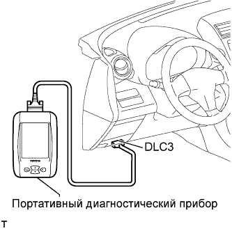
When using intelligent tester:
Connect the intelligent tester to the DLC3.
Allow the engine to idle.
Select the following menu items:
Powertrain / Engine and ECT / Data List / IGN Advance.Read IGN Advance to check the ignition timing.
- Standard ignition timing:
- 5 to 15° BTDC @ idle
Check that the ignition timing advances immediately when the engine speed is increased.
Turn the ignition switch off.
Disconnect the intelligent tester from the DLC3.
 |
When not using intelligent tester:
Remove the No. 1 engine cover (see page RAV4_ACA30 RM000001R3L001X_01_0005.html).
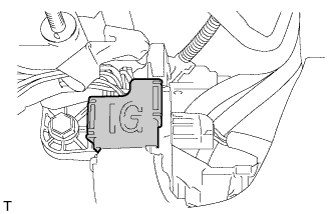
Open the ignition cover located in the right of the No. 4 ignition coil.
Pull out the wire harness from the IG cover.
Connect the timing light to the wire harness.
- ПРИМЕЧАНИЕ:
- Use a timing light that detects the first signal.
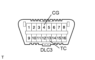
Using SST, connect terminals 13 (TC) and 4 (CG) of the DLC3.
- Специальный инструмент (SST):
- 09843-18040
Allow the engine to idle and check the ignition timing.
- Standard ignition timing:
- 8 to 12° BTDC @ idle
- УКАЗАНИЕ:
- Run the engine at 1,000 to 1,300 rpm for 5 seconds, then check that the engine speed returns to the idling speed.
Remove SST from the DLC3.
Allow the engine to idle and check the ignition timing.
- Standard ignition timing:
- 5 to 15° BTDC
Check that the ignition timing advances immediately when the engine speed is increased.
Turn the ignition switch off.
Remove the timing light.
Close the IG cover.
Install the No. 1 engine cover (see page RAV4_ACA30 RM000001AA9002X_01_0026.html).
| 49. INSPECT ENGINE IDLING SPEED |
When using intelligent tester:
Turn OFF all the accessories and air conditioning.
Move the shift lever to P or neutral.
Connect the intelligent tester to the DLC3.
Warm up the engine.
Select the tester menus:
Powertrain / Engine and ECT / Data List / Engine SPD.Read Engine SPD to check the idle speed while the radiator-cooling fan is not rotating.
- Standard idle speed:
Item Specified Condition A/T 600 to 700 rpm M/T 600 to 700 rpm
Turn the ignition switch off.
Disconnect the tester from the DLC3.
|
When not using intelligent tester:
Turn OFF all the accessories and air conditioning.
Move the shift lever to P or neutral.
Connect SST to 9 (TAC) of the DLC3 terminal, and then connect a tachometer to SST.
- Специальный инструмент (SST):
- 09843-18030
Warm up the engine.
Check the idle speed while the radiator-cooling fan is not rotating.
- Standard idle speed:
Item Specified Condition A/T 600 to 700 rpm M/T 600 to 700 rpm
Turn the ignition switch off.
Remove the tachometer and disconnect SST from the DLC3.

| 50. INSPECT COMPRESSION |
Warm up and stop the engine.
Remove the No. 1 engine under cover.
Remove the 4 ignition coils (see page RAV4_ACA30 RM000001QVM002X_01_0003.html).
Remove the 4 spark plugs.
Disconnect the 4 fuel injector connectors.
Set SST and a compression gauge.
- Специальный инструмент (SST):
- 09992-00500
 |
Insert the compression gauge into the spark plug hole.
While cranking the engine, measure the compression pressure.
- Standard compression pressure:
- 1,300 kPa (13.8 kgf/cm2, 196 psi)
- Minimum pressure:
- 1,000 kPa (10 kgf/cm2, 142 psi)
- Standard difference between each cylinder:
- 100 kPa (1.0 kgf/cm2, 14 psi)
- ПРИМЕЧАНИЕ:
- Always use a fully charged battery to obtain an engine speed of 250 rpm or more.
- Check the other cylinder's compression pressures in the same way.
- This measurement must be done as quickly as possible.
- УКАЗАНИЕ:
- If adding oil increases the compression, the piston rings and/or cylinder bore may be worn or damaged.
- If pressure stays low, a valve may be stuck or seated improperly, or there may be leakage in the gasket.
Connect the 4 fuel injector connectors.
Install the 4 spark plugs.
Install the 4 ignition coils (see page RAV4_ACA30 RM000001QVK002X_01_0001.html).
Install the No. 1 engine under cover.
| 51. INSPECT CO/HC |
- УКАЗАНИЕ:
- The ECM properly controls the CO/HC concentration in the emission gas.
Start and warm up the engine.
Run the engine at 2,500 rpm for approximately 180 seconds.
Insert the CO/HC meter testing probe at least 40 cm (1.3 ft.) into the tailpipe while idling.
Inspect the CO/HC concentration while idling and/or at 2,500 rpm.
If the CO/HC concentration is not as specified, perform troubleshooting in the order given below.See the table below for possible causes, and then inspect and repair the applicable causes if necessary.
CO HC Problems Causes Normal High Rough idle 1. Faulty ignition:
- Incorrect timing
- Plugs are contaminated, shorted, or gaps are defective
2. Incorrect valve clearance
3. Leaks in intake and exhaust valve
4. Leaks in cylindersLow High Rough idle
(Fluctuating HC reading)1. Vacuum leakage:
- Ventilation hoses
- Intake manifold
- Throttle body
- Brake booster line
2. Lean mixture causing misfireHigh High Rough idle
(Black smoke from exhaust)1. Restricted air filter
2. Plugged PCV valve
3. Faulty SFI system:
- Faulty pressure regulator
- Faulty engine coolant temperature sensor
- Faulty mass air flow meter
- Faulty ECM
- Faulty injectors
- Faulty throttle body
| 52. INSTALL NO. 1 ENGINE COVER |
Install the engine cover with the 2 nuts.
- Момент затяжки:
- 7.0 Н*м{71 кгс*см, 62 фунт-сила-дюймов}
 |
| 53. INSTALL FRONT FENDER APRON RH |
| 54. INSTALL NO. 1 ENGINE UNDER COVER |
| 55. INSTALL FRONT WHEEL RH |
| 56. INSTALL RADIATOR SUPPORT OPENING COVER |