Dtc C1248/48 Open Circuit In Rear Differential Lock
Brake. Hilux. Tgn26, 36 Kun25, 26, 35, 36 Ggn25
DESCRIPTION
WIRING DIAGRAM
INSPECTION PROCEDURE
CHECK TERMINAL VOLTAGE (EXI2 TERMINAL)
RECONFIRM DTC
INSPECT REAR DIFFERENTIAL LOCK POSITION SWITCH
CHECK HARNESS AND CONNECTOR (EXI2 TERMINAL CIRCUIT)
DTC C1248/48 Open Circuit in Rear Differential Lock |
DESCRIPTION
w/ Rear Differential Lock:The skid control ECU (brake actuator assembly) monitors the rear differential lock position switch (No. 4 transfer indicator switch) and if the rear differential is locked, at which time the rear differential lock indicator light is illuminated, the skid control ECU (brake actuator assembly) prohibits the ABS.At the same time, the skid control ECU (brake actuator assembly) illuminates the ABS warning light.DTC Code
| DTC Detection Condition
| Trouble Area
|
C1248/48
| At a vehicle speed of 50 km/h (31 mph) or more, 3 seconds or more elapse after the rear differential changes from free to lock.
- HINT:
- For vehicles without rear differential lock, this DTC may be stored due to an EXI2 terminal circuit malfunction.
| - w/ Rear Differential Lock:
- Rear differential lock position switch (No. 4 transfer indicator switch)
- Differential lock system
- EXI2 terminal circuit
- Skid control ECU (Brake actuator assembly)
|
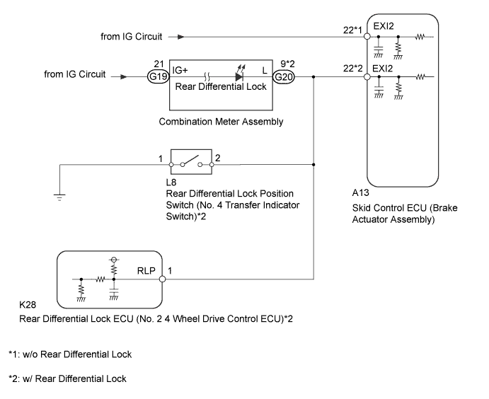
WIRING DIAGRAM
INSPECTION PROCEDURE
- NOTICE:
- Before disconnecting the connector, make sure that there are no problems with the connection.
- After disconnecting the connector, make sure that the connector case and terminals are not deformed or corroded.
| 1.CHECK TERMINAL VOLTAGE (EXI2 TERMINAL) |
w/ Rear Differential Lock:
Set the vehicle to the rear differential free state.
Turn the ignition switch off.
Disconnect the skid control ECU (brake actuator assembly) connector.
Measure the voltage according to the value(s) in the table below.
- Standard Voltage:
Tester Connection
| Switch Condition
| Specified Condition
|
A13-22 (EXI2) - Body ground
| Ignition switch ON
| 11 to 14 V
|
Text in Illustration*a
| Front view of wire harness connector
(to Skid Control ECU [Brake Actuator Assembly])
|
ResultResult
| Proceed to
|
OK
| A
|
NG (w/ Rear Differential Lock)
| B
|
NG (w/o Rear Differential Lock)
| C
|
| |
|
| | REPAIR OR REPLACE HARNESS OR CONNECTOR |
|
|
Clear the DTC (HILUX_TGN26 RM000000XHV0CFX.html).
Turn the ignition switch off.
Start the engine.
w/ Rear Differential Lock:
Set the vehicle to the rear differential free state.
Drive the vehicle at a speed of 50 km/h (31 mph) or more for 3 seconds or more.
Check if the same DTC is output (HILUX_TGN26 RM000000XHV0CFX.html).
ResultResult
| Proceed to
|
DTC output
| A
|
DTC not output
| B
|
| 3.INSPECT REAR DIFFERENTIAL LOCK POSITION SWITCH |
Turn the ignition switch off.
Remove the rear differential lock position switch (No. 4 transfer indicator switch) (HILUX_TGN26 RM000003ARU004X.html).
Inspect the rear differential lock position switch (No. 4 transfer indicator switch) (HILUX_TGN26 RM000001LZW015X_01_0008.html).
| 4.CHECK HARNESS AND CONNECTOR (EXI2 TERMINAL CIRCUIT) |
Turn the ignition switch off.
Disconnect the rear differential lock position switch (No. 4 transfer indicator switch) connector.
Disconnect the rear differential lock ECU (No. 2 4 wheel drive control ECU) connector.
Disconnect the skid control ECU (brake actuator assembly) connector.
Disconnect the G20 combination meter connector.
Measure the resistance according to the value(s) in the table below.
- Standard Resistance:
Tester Connection
| Condition
| Specified Condition
|
A13-22 (EXI2) - L8-2
| Always
| Below 1 Ω
|
A13-22 (EXI2) - G20-9 (L)
| Always
| Below 1 Ω
|
A13-22 (EXI2) - K28-1 (RLP)
| Always
| Below 1 Ω
|
A13-22 (EXI2) - Body ground
| Always
| 10 kΩ or higher
|
| | REPAIR OR REPLACE HARNESS OR CONNECTOR |
|
|