Propeller Shaft Assembly (For Tsam Made) -- Disassembly |
| 1. REMOVE REAR SLIDING SHAFT BOOT |
Place matchmarks on the propeller shaft and sleeve yoke.
Using a side cutter or pliers, remove the small and large boot clamps.
Disconnect the boot from the sleeve yoke.
Remove the sleeve yoke, and then remove the boot from the propeller shaft.
| 2. REMOVE UNIVERSAL JOINT SPIDER ASSEMBLY |
- HINT:
- Use the same procedure for all universal joint spiders.
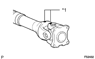
Place matchmarks on the yokes.
Text in Illustration *1 Matchmark
 |
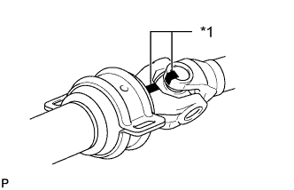
Place matchmarks on the center yoke and the part it is connected to (yoke or shaft).
Text in Illustration *1 Matchmark
 |
Using a brass bar and hammer, slightly tap in the spider bearing outer races.
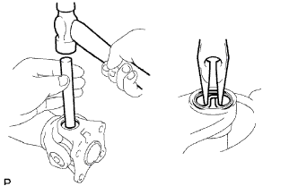 |
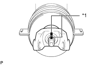
Using needle nose pliers, remove the 4 snap rings from the grooves.
Clamp the propeller shaft in a vise between aluminum plates.
- NOTICE:
- Do not overtighten the vise.
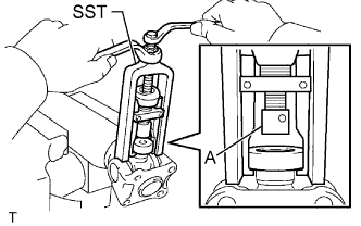 |
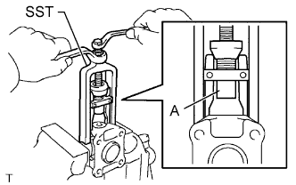
Using SST, push the sleeve yoke side spider bearing until: 1) the spider almost touches the sleeve yoke or propeller shaft, and 2) the spider bearing on the opposite side is partially pushed out.
- SST
- 09332-25010
- HINT:
- Before installing SST, sufficiently raise the part labeled A. If part A is too low, SST may be difficult to install.
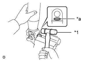
Clamp the pushed out spider bearing outer race in a vise between aluminum plates and tap the propeller shaft to remove the spider bearing.
Text in Illustration *1 Plastic-faced Hammer *a Hammering Point - NOTICE:
- Do not tap the shaft tube.
- Do not overtighten the vise.
- NOTICE:
- Do not tap the shaft tube.
- HINT:
- Use the same procedure to remove the spider bearing from the opposite side of the spider.
 |
Remove the flange yoke and spider from the propeller shaft.
Reinstall the 2 removed spider bearings to the spider and clamp the spider bearings in a vise between aluminum plates.
- NOTICE:
- Do not overtighten the vise.
 |
Using SST, push the flange yoke side spider bearing until: 1) the spider almost touches the flange yoke, and 2) the spider bearing on the opposite side is partially pushed out.
- SST
- 09332-25010
- HINT:
- Before installing SST, sufficiently raise the part labeled A. If part A is too low, SST may be difficult to install.
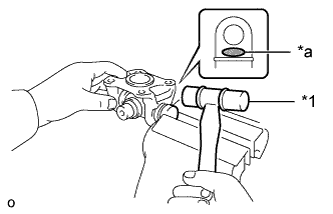
Clamp the pushed out spider bearing outer race in a vise between aluminum plates and tap the flange yoke to remove the spider bearing.
Text in Illustration *1 Plastic-faced Hammer *a Hammering Point - NOTICE:
- Do not overtighten the vise.
- HINT:
- Use the same procedure to remove the spider bearing from the opposite side of the spider.
 |
Separate the spider from the flange yoke.
| 3. REMOVE CENTER NO. 1 SUPPORT BEARING ASSEMBLY |
 |
Clamp the center yoke in a vise between aluminum plates.
Using a hammer and chisel, loosen the staked part of the nut and remove the nut and washer.
Place matchmarks on the intermediate shaft and center yoke.
Text in Illustration *1 Matchmark
 |
Using a brass bar and hammer, tap out the center yoke.
Remove the washer and center support bearing from the intermediate shaft.