Двигатель. Toyota Rav4. Aca30, 33, 38 Ala30
Система Управления Двигателем 2Ad-Ftv. Toyota Rav4. Aca30, 33, 38 Ala30
Ecd System -- Terminals Of Ecm |
| CHECK ECM |
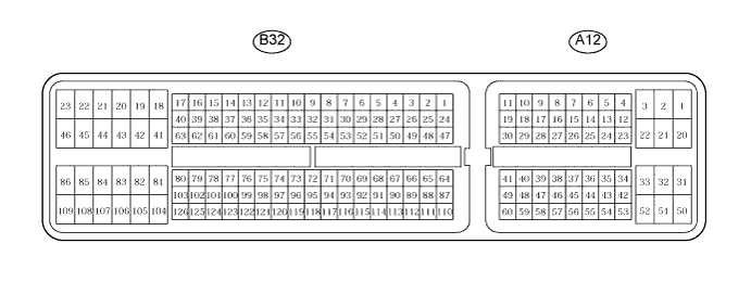
Measure the voltage of the ECM connector.
- УКАЗАНИЕ:
- Each ECM terminal's standard voltage is shown in the table below.
- In the table, first follow the information in "Condition". Look at "Symbols (Terminal No.)" for the terminals to be inspected. The standard voltage between the terminals is shown in "Specified Condition".
- Use the illustration above as a reference for the ECM terminals.
Symbols (Terminal No.) Wiring Color Terminal Description Condition Specified Condition BATT (A12-2) - E1 (B32-109) W - BR Battery (for measuring the battery voltage and for the ECM memory) Always 9 to 14 V IGSW (A12-25) - E1 (B32-109) B - BR Ignition switch Ignition switch on (IG) 9 to 14 V +B (A12-1) - E1 (B32-109) B - BR Power source of ECM Ignition switch on (IG) 9 to 14 V MREL (A12-45) - E1 (B32-109) O - BR EFI MAIN relay Ignition switch on (IG) 9 to 14 V MREL (A12-45) - E1 (B32-109) O - BR EFI MAIN relay 2 seconds elapsed after ignition switch off 0 to 1.5 V IREL (A12-44) - E1 (B32-109) R - BR EDU relay ignition switch off 9 to 14 V IREL (A12-44) - E1 (B32-109) R - BR EDU relay Idling 0 to 1.5 V GREL (B32-56) - E1 (B32-109) L - BR Glow plug relay Cranking 9 to 14 V GREL (B32-56) - E1 (B32-109) L - BR Glow plug relay Idling (Engine start after 10 minutes or more) 0 to 1.5 V VPA (A12-53) - EPA (A12-57) W - Y Accelerator pedal position sensor (for engine control) Ignition switch on (IG), accelerator pedal fully released 0.5 to 1.1 V VPA (A12-53) - EPA (A12-57) W - Y Accelerator pedal position sensor (for engine control) Ignition switch on (IG), accelerator pedal fully depressed 3.0 to 4.6 V VPA2 (A12-54) - EPA2 (A12-58) R - O Accelerator pedal position sensor (for sensor malfunction detection) Ignition switch on (IG), accelerator pedal fully released 0.9 to 2.3 V VPA2 (A12-54) - EPA2 (A12-58) R - O Accelerator pedal position sensor (for sensor malfunction detection) Ignition switch on (IG), accelerator pedal fully depressed 3.4 to 5.0 V VCPA (A12-55) - EPA (A12-57) B - Y Power source of accelerator pedal position sensor (for VPA1) Ignition switch on (IG) 4.5 to 5.5 V VCP2 (A12-56) - EPA2 (A12-58) L - O Power source of accelerator pedal position sensor (for VPA2) Ignition switch on (IG) 4.5 to 5.5 V STAR (B32-53)* - E1 (B32-109) W - BR ST relay control Cranking 9 to 14 V STA (A12-43) - E1 (B32-109) LG - BR Starter signal Cranking 6.0 V or more INJF (B32-51) - E1 (B32-109) P - BR EDU Idling Pulse generation
(see waveform 3)#1 (B32-50) - E1 (B32-109)
#2 (B32-49) - E1 (B32-109)
#3 (B32-48) - E1 (B32-109)
#4 (B32-47) - E1 (B32-109)GR - BR
G - BR
LG - BR
L - BRInjector Idling Pulse generation
(see waveform 2)NE+ (B32-78) - NE- (B32-77) B - W Crankshaft position sensor Idling Pulse generation
(see waveform 4)G+ (B32-80) - G- (B32-79) R - G Camshaft position sensor Idling Pulse generation
(see waveform 4)STP (A12-35) - E1 (B32-109) L - BR Normally open switch Ignition switch on (IG), brake pedal depressed 7.5 to 14 V STP (A12-35) - E1 (B32-109) L - BR Normally open switch Ignition switch on (IG), brake pedal released 0 to 1.5 V ST1- (A12-34) - E1 (B32-109) GR - BR Normally closed switch Ignition switch on (IG), brake pedal depressed 0 to 1.5 V ST1- (A12-34) - E1 (B32-109) GR - BR Normally closed switch Ignition switch on (IG), brake pedal released 7.5 to 14 V TC (A12-26) - E1 (B32-109) G - BR Terminal TC of DLC3 Ignition switch on (IG) 9 to 14 V W (A12-12) - E1 (B32-109) R - BR MIL MIL illuminated 0 to 3 V W (A12-12) - E1 (B32-109) R - BR MIL MIL not illuminated 9 to 14 V SPD (A12-14) - E1 (B32-109) V - BR Speed signal from combination meter Ignition switch on (IG), drive wheels are rotating slowly Pulse generation
(see waveform 7)PIM (B32-117) - EPIM (B32-94) G - BR Manifold absolute pressure sensor Apply negative pressure of 40 kPa (300 mmHg, 11.8 in.Hg) 0.3 to 0.9 V PIM (B32-117) - EPIM (B32-94) G - BR Manifold absolute pressure sensor Same as atmospheric pressure 0.8 to 1.4 V PIM (B32-117) - EPIM (B32-94) G - BR Manifold absolute pressure sensor Apply positive pressure of 69 kPa (518 mmHg, 20.3 in.Hg) 1.6 to 2.2 V TACH (A12-13) - E1 (B32-109) GR - BR Engine speed Idling Pulse generation
(see waveform 8)PCR1 (B32-67) - E2M (B32-91) P - BR Common rail pressure sensor (main) Idling 1.8 to 2.1 V ALT (B32-54) - E1 (B32-109) B - BR Generator duty ratio Idling Pulse generation
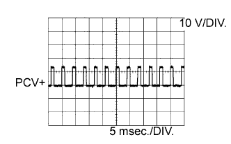
(see waveform 9)PCV+ (B32-42) - PCV- (B32-41) LG - R Suction control valve Idling Pulse generation
(see waveform 1)VN (B32-84) - E1 (B32-109) Y - BR VRV (for VN turbocharger) Ignition switch on (IG) Pulse generation
(see waveform 5)VLU (B32-119) - EVLU (B32-96) G - BR Throttle position sensor Ignition switch on (IG), throttle valve fully opened 2.8 to 3.8 V LUSL (B32-86) - E1 (B32-109) V - BR Throttle valve duty signal Engine warmed up, engine racing Pulse generation
(see waveform 6)EGLS (B32-118) - EEGL (B32-95) GR - BR EGR valve position sensor Ignition switch on (IG) 0.6 to 1.4 V EGRS (B32-85) - E1 (B32-109) W - BR EGR Engine warmed up, idling Pulse generation
(see waveform 10)THIA (B32-113) - ETHI (B32-90) Y - BR Intake air temperature sensor (Intake manifold) Idling, intake air temperature at 0 to 80°C (32 to 176°F) 0.5 to 3.4 V THF (B32-112) - ETHF (B32-89) GR - BR Fuel temperature sensor Ignition switch on (IG) 0.5 to 3.4 V THW (B32-111) - ETHW (B32-88) B - BR ECT sensor Idling, engine coolant temperature at 60 to 120°C (140 to 248°F) 0.2 to 1.0 V VG (B32-65) - EVG (B32-64) LG - W MAF meter power source Engine idling 0.5 to 3.4 V THA (B32-110) - ETHA (B32-87) L - BR IAT sensor Idling, intake air temperature at 0 to 80°C (32 to 176°F) 0.5 to 3.4 V FANL (A12-22) - E1 (B32-109) R - BR FAN NO. 3 relay Ignition switch on (IG) 9 to 14 V FANL (A12-22) - E1 (B32-109) R - BR FAN NO. 3 relay Idling with A/C ON
or
High engine coolant temperatureBelow 1.5 V FANH (A12-21) - E1 (B32-109) W - BR FAN NO. 1, 2 relay Idling with high engine coolant temperature Below 1.5 V ACCR (A12-24)* - E1 (B32-109) LG - BR Accessory power cut signal Ignition switch on (IG) → Cranking Below 1.5 V STSW (A12-9)* - E1 (B32-109) R - BR Engine cranking required signal Ignition switch on (IG) → Cranking Below 1 V → 9 to 14 V momentary VCIB (B32-70) - EIB (B32-93) R - BR Battery current sensor Ignition switch on (IG) 4.5 to 5.0 V IB (B32-116) - EIB (B32-93) B - BR Battery current sensor Ignition switch on (IG) 0.5 to 4.5 V THB (B32-115) - EIB (B32-93) LG - BR Battery current sensor Ignition switch on (IG) 0.5 to 4.5 V CANH (A12-38) - E1 (B32-109) Y - BR CAN communication line Ignition switch on (IG) Pulse generation
(see waveform 11)CANL (A12-46) - E1 (B32-109) W - BR CAN communication line Ignition switch on (IG) Pulse generation
(see waveform 12)- УКАЗАНИЕ:
- *: w/ Entry and start system.
Using an oscilloscope, check the waveform 1.
- Waveform 1:
- Suction control valve signal
Item Content Symbols (Terminal No.) PCV+ (B32-42) - PCV- (B32-41) Tool Setting 10 V/DIV., 5 msec./DIV. Condition Idling or cranking with warm engine
- УКАЗАНИЕ:
- The waveform varies depending on the suction control valve operation.
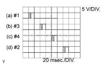
Using an oscilloscope, check the waveform 2.
- Waveform 2:
- No. 1 injector injection signal
No. 2 injector injection signal
No. 3 injector injection signal
No. 4 injector injection signal Item Content Symbols (Terminal No.) (a) #1 (B32-50) - E1 (B32-109)
(b) #3 (B32-49) - E1 (B32-109)
(c) #4 (B32-48) - E1 (B32-109)
(d) #2 (B32-47) - E1 (B32-109)Tool Setting 5 V/DIV., 20 msec./DIV. Condition Idling with warm engine
- УКАЗАНИЕ:
- The waveform varies depending on the injector injection.
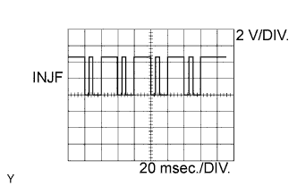
Using an oscilloscope, check the waveform 3.
- Waveform 3:
- Injector injection confirmation signal
Item Content Symbols (Terminal No.) INJF (B32-51) - E1 (B32-109) Tool Setting 2 V/DIV., 20 msec./DIV. Condition Idling with warm engine
- УКАЗАНИЕ:
- The waveform varies depending on the injector injection.
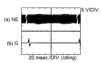
Using an oscilloscope, check the waveform 4.
- Waveform 4:
- Crankshaft position sensor signal
- Camshaft position sensor signal
Item Content Symbols (Terminal No.) (a) NE+ (B32-78) - NE- (B32-77)
(b) G+ (B32-80) - G- (B32-79)Tool Setting 5 V/DIV., 20 msec./DIV. Condition Idling with warm engine
- УКАЗАНИЕ:
- The waveform varies depending on the engine revolution.
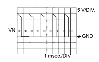
Using an oscilloscope, check the waveform 5.
- Waveform 5:
- VRV for turbocharger control signal
Item Content Symbols (Terminal No.) VN (B32-84) - E1 (B32-109) Tool Setting 5 V/DIV., 1 msec./DIV. Condition Idling with warm engine
- УКАЗАНИЕ:
- The waveform changes depending on the electric vacuum regulating valve for turbocharger operation.
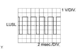
Using an oscilloscope, check the waveform 6.
- Waveform 6:
- Diesel throttle signal
Item Content Symbols (Terminal No.) LUSL (B32-86) - E1 (B32-109) Tool Setting 1 V/DIV., 2 msec./DIV. Condition Warm engine with engine racing
- УКАЗАНИЕ:
- The waveform varies depending on the throttle valve operation.
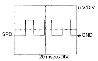
Using an oscilloscope, check the waveform 7.
- Waveform 7:
- Vehicle speed signal
Item Content Symbols (Terminal No.) SPD (A12-14) - E1 (B32-109) Tool Setting 5 V/DIV., 20 msec./DIV. Condition Driving the vehicle
- УКАЗАНИЕ:
- The wavelength becomes shorter as the vehicle speed increases.
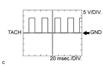
Using an oscilloscope, check the waveform 8.
- Waveform 8:
- Engine speed signal
Item Content Symbols (Terminal No.) TACH (A12-13) - E1 (B32-109) Tool Setting 5 V/DIV., 20 msec./DIV. Condition Idling with warm engine
- УКАЗАНИЕ:
- The wavelength becomes shorter as the engine speed increases.
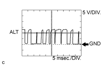
Using an oscilloscope, check the waveform 9.
- Waveform 9:
- Generator signal
Item Content Symbols (Terminal No.) ALT (B32-54) - E1 (B32-109) Tool Setting 5 V/DIV., 5 msec./DIV. Condition Idling
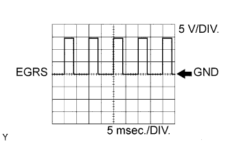
Using an oscilloscope, check the waveform 10.
- Waveform 10:
- EGR position sensor signal
Item Content Symbols (Terminal No.) EGRS (B32-85) - EEGL (B32-95) Tool Setting 5 V/DIV., 5 msec./DIV. Condition Idling
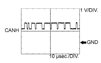
Using an oscilloscope, check the waveform 11.
- Waveform 11:
- CAN communication signal
Item Content Symbols (Terminal No.) CANH (A12-38) - E1 (B32-109) Tool Setting 1 V/DIV., 10 μsec./DIV. Condition Engine stopped and ignition switch on (IG)
- УКАЗАНИЕ:
- The waveform varies depending on the CAN communication signal.
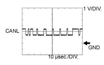
Using an oscilloscope, check the waveform 12.
- Waveform 12:
- CAN communication signal
Item Content Symbols (Terminal No.) CANL (A12-46) - E1 (B32-109) Tool Setting 1 V/DIV., 10 μsec./DIV. Condition Engine stopped and ignition switch on (IG)
- УКАЗАНИЕ:
- The waveform varies depending on the CAN communication signal.
 |
 |
 |
 |
 |
 |
 |
 |
 |
 |
 |
 |