Dtc P0504 Brake Switch A / B Correlation
DESCRIPTION
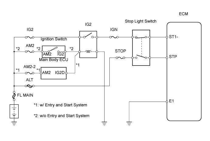
WIRING DIAGRAM
INSPECTION PROCEDURE
CHECK STOP LIGHT SWITCH
CHECK STP SIGNAL
INSPECT STOP LIGHT SWITCH
CHECK WIRE HARNESS (STOP LIGHT SWITCH - ECM)
DTC P0504 Brake Switch "A" / "B" Correlation |
DESCRIPTION
In this system, the signals of the duplex type stop light switch (STP and ST1-) are used to judge whether the brake system is abnormal. When signals that indicate depressing and releasing the brake pedal are detected simultaneously, the ECM interprets this as a malfunction of the stop light switch.- УКАЗАНИЕ:
- Normal conditions are shown in the table below.
Signal
| Brake Pedal Released
| In Transition
| Brake Pedal Depressed
|
STP
| OFF
| ON
| ON
|
ST1-
| ON
| ON
| OFF
|
DTC No.
| DTC Detection Condition
| Trouble Area
|
P0504
| Conditions (a), (b) and (c) continue for 0.5 seconds or more:
(1 trip detection logic)
(a) Ignition switch is on (IG)
(b) Brake pedal is released
(c) STP signal is OFF when ST1- signal is OFF
| - Short in stop light switch signal circuit
- Stop light switch
- ECM
|
WIRING DIAGRAM
INSPECTION PROCEDURE
- ПРИМЕЧАНИЕ:
- After replacing the ECM, the new ECM needs registration (see page RAV4_ACA30 RM000000TJ4007X.html) and initialization (see page RAV4_ACA30 RM000000TIN007X.html).
| 1.CHECK STOP LIGHT SWITCH |
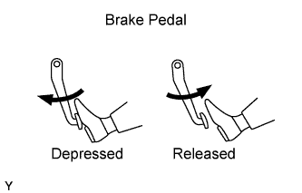
Check if the stop lights turn ON and OFF when the brake pedal is depressed and released.
- OK:
- Stop lights turn ON and OFF normally.
| | REPAIR OR REPLACE STOP LIGHT SWITCH |
|
|
Connect the intelligent tester to the DLC3.
Turn the ignition switch on (IG) and turn the tester ON.
Enter the following menus: Powertrain / Engine and ECT / Data List / Stop Light Switch.
Check the result.
- OK:
Brake Pedal
| Specified Condition
|
Depressed
| STP signal ON
|
Released
| STP signal OFF
|
| | CHECK FOR INTERMITTENT PROBLEMS |
|
|
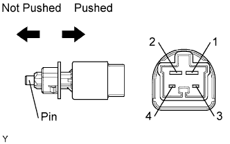
| 3.INSPECT STOP LIGHT SWITCH |
Disconnect the A5 stop light switch connector.
Measure the resistance of the stop light switch.
- Standard resistance:
Tester Connection
| Switch Condition
| Specified Condition
|
1 - 2
| Pin not pushed
| Below 1 Ω
|
3 - 4
| Pin not pushed
| 10 kΩ or higher
|
1 - 2
| Pin pushed
| 10 kΩ or higher
|
3 - 4
| Pin pushed
| Below 1 Ω
|
Reconnect the stop light switch connector.
| | REPLACE STOP LIGHT SWITCH |
|
|
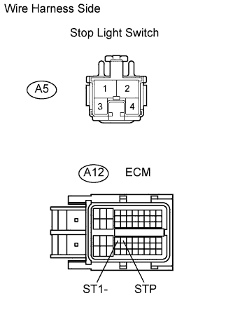
| 4.CHECK WIRE HARNESS (STOP LIGHT SWITCH - ECM) |
Disconnect the A5 stop light switch connector.
Disconnect the A12 ECM connector.
Measure the resistance of the wire harness side connectors.
- Standard resistance:
Tester Connection
| Specified Condition
|
A5-1 - A12-35 (STP)
| Below 1 Ω
|
A5-4 - A12-34 (ST1-)
| Below 1 Ω
|
A5-1 or A12-35 (STP) - Body ground
| 10 kΩ or higher
|
A5-4 or A12-34 (ST1-) - Body ground
| 10 kΩ or higher
|
Reconnect the stop light switch connector.
Reconnect the ECM connector.
| | REPAIR OR REPLACE HARNESS AND CONNECTOR |
|
|