Drivetrain. Hilux. Tgn26, 36 Kun25, 26, 35, 36 Ggn25
DESCRIPTION
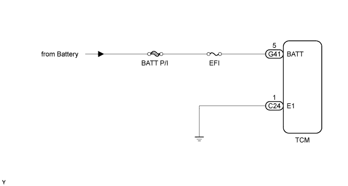
WIRING DIAGRAM
INSPECTION PROCEDURE
CHECK DTC OUTPUT (ECD SYSTEM DTC P0560)
CHECK TCM (BATTERY, GROUND)
DESCRIPTION
The battery supplies power to the TCM even when the ignition switch is off. This power allows the TCM to store data such as DTC history, freeze frame data and fuel trim values. If the battery voltage falls below a minimum level, the TCM data is cleared and the TCM determines that there is a malfunction in the power supply circuit. The next time the engine is started, the TCM will illuminate the MIL and store the DTC.DTC Code
| DTC Detection Condition
| Trouble Area
|
P0560
| Open in the TCM back-up power source circuit (1-trip detection logic).
| - Open in back-up power source circuit
- TCM
|
- HINT:
- If DTC P0560 is stored, the TCM does not store other DTCs.
WIRING DIAGRAM
INSPECTION PROCEDURE
| 1.CHECK DTC OUTPUT (ECD SYSTEM DTC P0560) |
Connect the intelligent tester to the DLC3.
Turn the ignition switch to ON.
Turn the intelligent tester on.
Enter the following menus: Powertrain / Engine / DTC.
Read the DTCs using the intelligent tester.
ResultResult
| Proceed to
|
DTCs are not output
| A
|
P0560 is output (ECD system w/ EGR cooler)
| B
|
P0560 is output (ECD system w/o EGR cooler)
| C
|
| 2.CHECK TCM (BATTERY, GROUND) |
Disconnect the G41 and C24 TCM connectors.
Measure the voltage according to the value(s) in the table below.
- Standard Voltage:
Tester Connection
| Condition
| Specified Condition
|
G41-5 (BATT) - Body ground
| Always
| 11 to 14 V
|
Measure the resistance according to the value(s) in the table below.
- Standard Resistance:
Tester Connection
| Condition
| Specified Condition
|
C24-1 (E1) - Body ground
| Always
| Below 1 Ω
|
Text in Illustration*a
| Rear view of wire harness connector
(to TCM)
|
| | REPAIR OR REPLACE HARNESS OR CONNECTOR (TCM - BATTERY, GROUND) |
|
|