Drivetrain. Hilux. Tgn26, 36 Kun25, 26, 35, 36 Ggn25
A340F Automatic Transmission Transaxle. Hilux. Tgn26, 36 Kun25, 26, 35, 36 Ggn25
Automatic Transmission System -- Terminals Of Ecu |
| CHECK TCM |

- HINT:
- The standard voltage at each TCM terminal is shown in the table below.
- In the table, first follow the information under "Condition". Look under "Terminal No. (Symbol)" for the terminals to inspect. The standard voltage between the terminals is shown under "Specified Condition".
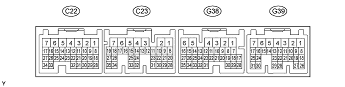
- Use the illustration above as a reference for the TCM terminals.
| Terminal No. (Symbol) | Wiring Color | Terminal Description | Condition | Specified Condition |
| C24-12 (NSW) - C24-1 (E1) | L-Y - BR | PNP switch signal |
| Below 1 V |
| 11 to 14 V | |||
| G40-9 (R) - C24-1 (E1) | R-Y - BR | R shift position switch signal |
| 11 to 14 V |
| Below 1 V | |||
| G40-8 (D) - C24-1 (E1) | G-Y - BR | D shift position switch signal |
| 11 to 14 V |
| Below 1 V | |||
| G40-12 (3) - C24-1 (E1) | G-O - BR | 3 shift position switch signal |
| 11 to 14 V |
| Below 1 V | |||
| G40-11 (2) - C24-1 (E1) | L - BR | 2 shift position switch signal |
| 11 to 14 V |
| Below 1 V | |||
| G40-10 (L) - C24-1 (E1) | G-R - BR | L shift position switch signal |
| 11 to 14 V |
| Below 1 V | |||
| C24-18 (S1) - C24-1 (E1) | GR - BR | S1 solenoid signal | 1st or 2nd gear | 11 to 14 V |
| 3rd or 4th gear | Below 1 V | |||
| C24-17 (S2) - C24-1 (E1) | W-L - BR | S2 solenoid signal | 2nd or 3rd gear | 11 to 14 V |
| 1st or 4th gear | Below 1 V | |||
| C24-20 (SLT+) - C24-19 (SLT-) | G-Y - L-B | SLT solenoid signal | Engine idling | Pulse generation |
| C24-16 (SL) - C24-1 (E1) | G - BR | SL solenoid signal | Vehicle speed 65 km/h (40 mph), lockup (ON to OFF) | Pulse generation (See waveform 1) |
| Vehicle driving under look-up condition | 11 to 14 V | |||
| C24-24 (THOC) - C24-23 (E2) | BR - B-Y | ATF temperature sensor signal | ATF temperature: 115°C (239°F) or higher | Below 1.5 V |
| C24-30 (SP2+) - C24-29 (SP2-) | R - G | Speed sensor SP2 signal | Vehicle speed 20 km/h (12 mph) | Pulse generation (See waveform 2) |
| C24-3 (NC0+) - C24-2 (NC0-) | V - P | Speed sensor NC0 signal | Engine idling (shift lever in P or N) | Pulse generation (See waveform 3) |
| G40-15 (L4) - C24-1 (E1) | G-W - BR | L4 position signal |
| Below 1 V |
| 11 to 14 V | |||
| G41-25 (SPD1) - C24-1 (E1) | V-R - BR | Speed signal | Vehicle speed 20 km/h (12 mph) | Pulse generation (See waveform 4) |
| G41-14 (STP) - C24-1 (E1) | G-W - BR | STP light switch signal | Brake pedal is depressed | 7.5 to 14 V |
| Brake pedal is released | Below 1 V | |||
| C24-11 (STA) - C24-1 (E1) | B-Y - BR | Starter signal | Cranking | 6 V or more |
| G40-16 (TFN) - C24-1 (E1) | W-G - BR | N shift position switch signal |
| Below 1 V |
| 11 to 14 V | |||
| G41-6 (IG2) - C24-1 (E1) | B-O - BR | Ignition switch | Ignition switch ON | 11 to 14 V |
| G41-21 (CAN+) - C24-1 (E1) | V - BR | CAN communication line | Ignition switch ON | Pulse generation (See waveform 5) |
| G41-20 (CAN-) - C24-1 (E1) | P - BR | CAN communication line | Ignition switch ON | Pulse generation (See waveform 6) |
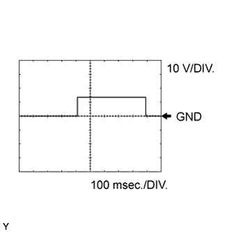
Using an oscilloscope, check waveform 1.
Reference Terminal No. (Symbol) Tool Setting Condition C24-16 (SL) - C24-1 (E1) 10 V/DIV., 100 msec./DIV. Vehicle speed 65 km/h (40 mph), lockup (ON to OFF) Using an oscilloscope, check waveform 2.
Reference Terminal No. (Symbol) Tool Setting Condition C24-30 (SP2+) - C24-29 (SP2-) 2 V/DIV., 20 msec./DIV. Vehicle speed 20 km/h (12 mph) Using an oscilloscope, check waveform 3.
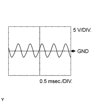
Reference Terminal No. (Symbol) Tool Setting Condition C24-3 (NC0+) - C24-2 (NC0-) 5 V/DIV., 0.5 msec./DIV. Engine idling (shift lever in P or N) Using an oscilloscope, check waveform 4.
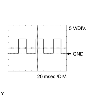
Reference Terminal No. (Symbol) Tool Setting Condition G41-25 (SPD1) - C24-1 (E1) 5 V/DIV., 20 msec./DIV. Vehicle speed 20 km/h (12 mph) Using an oscilloscope, check waveform 5.
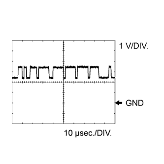
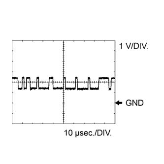
Reference Terminal No. (Symbol) Tool Setting Condition G41-21 (CAN+) - C24-1 (E1) 1 V/DIV., 10 μsec./DIV. Ignition switch ON Using an oscilloscope, check waveform 6.
Reference Terminal No. (Symbol) Tool Setting Condition G41-20 (CAN-) - C24-1 (E1) 1 V/DIV., 10 μsec./DIV. Ignition switch ON
 |
 |
 |
 |
 |
 |
| CHECK ECM |
- HINT:
- The standard voltage at each ECM terminal is shown in the table below.
- In the table, first follow the information under "Condition". Look under "Terminal No. (Symbol)" for the terminals to inspect. The standard voltage between the terminals is shown under "Specified Condition".
- Use the illustration above as a reference for the ECM terminals.
| Terminal No. (Symbol) | Wiring Color | Terminal Description | Condition | Specified Condition |
| G39-1 (+B) - C23-7 (E1) | B - BR | Power source of ECM | Ignition switch ON | 11 to 14 V |
| G38-22 (CAN+) - C23-7 (E1) | V - BR | CAN communication line | Ignition switch ON | Pulse generation (See waveform 1) |
| G38-21 (CAN-) - C23-7 (E1) | P - BR | CAN communication line | Ignition switch ON | Pulse generation (See waveform 2) |
Using an oscilloscope, check waveform 1.
Reference Terminal No. (Symbol) Tool Setting Condition G38-22 (CAN+) - C23-7 (E1) 1 V/DIV., 10 μsec./DIV. Ignition switch ON Using an oscilloscope, check waveform 2.
Reference Terminal No. (Symbol) Tool Setting Condition G38-21 (CAN-) - C23-7 (E1) 1 V/DIV., 10 μsec./DIV. Ignition switch ON
|
|