Cruise Control System Cruise Control Switch Circuit
DESCRIPTION
WIRING DIAGRAM
INSPECTION PROCEDURE
READ VALUE USING INTELLIGENT TESTER (CRUISE CONTROL MAIN SWITCH)
INSPECT CRUISE CONTROL MAIN SWITCH
INSPECT CRUISE CONTROL SWITCH WIRE
INSPECT SPIRAL CABLE SUB-ASSEMBLY
CHECK HARNESS AND CONNECTOR (SPIRAL CABLE - ECM AND BODY GROUND)
CRUISE CONTROL SYSTEM - Cruise Control Switch Circuit |
DESCRIPTION
This circuit sends a signal to the ECM depending on the cruise control main switch condition. The battery supplies positive (+) battery voltage to the cruise control main switch. Terminal 21 (CCS) of the ECM receives the voltage which varies according to the switch condition.
WIRING DIAGRAM
INSPECTION PROCEDURE
| 1.READ VALUE USING INTELLIGENT TESTER (CRUISE CONTROL MAIN SWITCH) |
Using the intelligent tester, read the Data List (HILUX_TGN26 RM000000PM306GX.html).
Cruise ControlTester Display
| Measurement Item/Range
| Normal Condition
| Diagnostic Note
|
CCS Main SW M-CPU
| Cruise control main switch signal (Main CPU) / ON or OFF
| ON: Cruise control main switch (Main CPU) on
OFF: Cruise control main switch (Main CPU) off
| -
|
Cancel Switch
| CANCEL switch signal / ON or OFF
| ON: CANCEL switch on
OFF: CANCEL switch off
| -
|
SET/COAST Switch
| SET / COAST switch signal / ON or OFF
| ON: -SET switch on
OFF: -SET switch off
| -
|
RES/ACC Switch
| RES / ACC switch signal / ON or OFF
| ON: +RES switch on
OFF: +RES switch off
| -
|
- OK:
- The display is as specified in the normal condition column.
| 2.INSPECT CRUISE CONTROL MAIN SWITCH |
Remove the cruise control main switch (HILUX_TGN26 RM000000VQ3069X.html).
Measure the resistance according to the value(s) in the table below.
- Standard Resistance:
Tester Connection
| Switch Condition
| Specified Condition
|
3 (CCS) - 1 (ECC)
| Cruise control main switch on
| Below 2.5 Ω
|
Cruise control main switch off
| 1 MΩ or higher
|
+RES switch held on
| 235 to 245 Ω
|
-SET switch held on
| 617 to 643 Ω
|
CANCEL switch held on
| 1509 to 1571 Ω
|
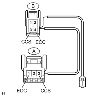
| 3.INSPECT CRUISE CONTROL SWITCH WIRE |
Remove the cruise control switch wire.
Measure the resistance according to the value(s) in the table below.
- Standard Resistance:
Tester Connection
| Condition
| Specified Condition
|
A-3 (CCS) - B-3 (CCS)
| Always
| Below 1 Ω
|
A-1 (ECC) - B-4 (ECC)
|
| | REPLACE CRUISE CONTROL SWITCH WIRE |
|
|
| 4.INSPECT SPIRAL CABLE SUB-ASSEMBLY |
Remove the spiral cable (HILUX_TGN26 RM0000010B200SX.html).
If there are any defects as follows, replace the spiral cable with a new one: scratches, cracks, dents or chips on the connector or spiral cable.
Check the spiral cable.
Set the spiral cable to the center position (HILUX_TGN26 RM0000010AZ00SX.html).
Rotate the spiral cable 2.5 times clockwise and measure the resistance according to the value(s) in the table below. Then rotate the spiral cable 5 times counterclockwise and measure the resistance according to the value(s) in the table below.
- NOTICE:
- As the spiral cable may break, do not rotate the spiral cable more than the specified amount.
- Standard Resistance:
Tester Connection
| Condition
| Specified Condition
|
A-1 (CCS) - B-3 (CCS)
| Always
| Below 1 Ω
|
A-2 (ECC) - B-4 (ECC)
|
Set the spiral cable to the center position and rotate the spiral cable 2.5 times clockwise. Then, while rotating the spiral cable 5 times counterclockwise, measure the resistance according to the value(s) in the table below.
- Standard Resistance:
Tester Connection
| Condition
| Specified Condition
|
A-1 (CCS) - B-3 (CCS)
| Always
| Below 1 Ω
|
A-2 (ECC) - B-4 (ECC)
|
| 5.CHECK HARNESS AND CONNECTOR (SPIRAL CABLE - ECM AND BODY GROUND) |
Disconnect the G12 spiral cable connector.
Disconnect the G39 ECM connector.
Measure the resistance according to the value(s) in the table below.
- Standard Resistance:
Tester Connection
| Condition
| Specified Condition
|
G12-1 (CCS) - G39-21 (CCS)
| Always
| Below 1 Ω
|
G12-2 (ECC) - Body ground
|
G12-1 (CCS) - Body ground
| Always
| 10 kΩ or higher
|
| | REPAIR OR REPLACE HARNESS OR CONNECTOR |
|
|