Intake Manifold -- Installation |
| 1. INSTALL STUD BOLT |
- HINT:
- If a stud bolt is deformed or its threads are damaged, replace it.
Using an E7 "TORX" socket wrench, install the stud bolts.
- Torque:
- 8.0 N*m{82 kgf*cm, 71 in.*lbf}
| 2. INSTALL INTAKE MANIFOLD |
Set 2 new gaskets on each cylinder head.
- NOTICE:
- Align the port holes of the gasket and cylinder head.
- Make sure the gaskets are installed facing the proper direction.
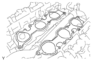 |
Set the intake manifold on the cylinder heads.
Install and uniformly tighten the 10 bolts in several passes.
- Torque:
- 26 N*m{265 kgf*cm, 19 ft.*lbf}
- HINT:
- Tighten the inner installation bolts of the intake manifold before tightening the outer bolts.
| 3. INSTALL FUEL DELIVERY PIPE SUB-ASSEMBLY |
Place the fuel delivery pipe together with the 6 fuel injectors on the intake manifold.
Temporarily install the 6 bolts which are used to hold the fuel delivery pipe to the intake manifold.
Check that the fuel injectors rotate smoothly.
If the fuel injectors do not rotate smoothly, replace the O-ring of any fuel injector that does not rotate smoothly.Text in Illustration *1 Connector 
Turn
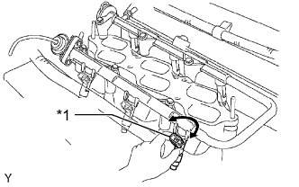 |
Position the fuel injector connector outward.
Tighten the 6 bolts which are used to hold the fuel delivery pipe to the intake manifold.
- Torque:
- 15 N*m{153 kgf*cm, 11 ft.*lbf}
Connect the 6 fuel injector connectors.
| 4. CONNECT NO. 2 FUEL PIPE SUB-ASSEMBLY |
Connect the No. 2 fuel pipe sub-assembly (HILUX_TGN26 RM000000YL401PX.html).
| 5. CONNECT NO. 1 FUEL PIPE SUB-ASSEMBLY |
Connect the No. 1 fuel pipe sub-assembly (HILUX_TGN26 RM000000YL401PX.html).
| 6. INSTALL INTAKE AIR SURGE TANK |
- NOTICE:
- Do not apply oil to the bolts and nuts listed below: :
Oil Application Prohibited Bolts for surge tank and intake manifold Nuts for surge tank and intake manifold
Install a new gasket to the intake air surge tank.
Using an 8 mm hexagon wrench, install the intake air surge tank with the 4 bolts and 2 nuts. Tighten the bolts and nuts in the order shown in the illustration.
- Torque:
- 28 N*m{286 kgf*cm, 21 ft.*lbf}
Text in Illustration Bolt 
Nut
 |
Install the water hose sub-assembly to the intake air surge tank with the 2 bolts.
- Torque:
- 5.4 N*m{55 kgf*cm, 48 in.*lbf}
Install the No. 2 surge tank stay with the 2 bolts.
- Torque:
- 21 N*m{214 kgf*cm, 15 ft.*lbf}
Install the No. 1 surge tank stay with the 2 bolts.
- Torque:
- 21 N*m{214 kgf*cm, 15 ft.*lbf}
Install the oil baffle plate with the bolt.
- Torque:
- 9.0 N*m{92 kgf*cm, 80 in.*lbf}
Install the throttle body bracket with the 2 bolts.
- Torque:
- 21 N*m{214 kgf*cm, 15 ft.*lbf}
Attach the 3 wire harness clamps and disconnect the wire harness.
Connect the throttle body connector.
Connect the vacuum switching valve (for ACIS) connector.
Connect the purge VSV connector.
Connect the No. 1 PCV hose.
Connect the vacuum hose.
Connect the purge line hose.
Connect the No. 5 water by-pass hose.
Connect the No. 4 water by-pass hose.
| 7. INSTALL NO. 2 AIR CLEANER HOSE |
Install the No. 2 air cleaner hose with the 2 bolts.
- Torque:
- 14 N*m{143 kgf*cm, 10 ft.*lbf}
| 8. INSTALL AIR CLEANER ASSEMBLY |
Install the air cleaner with the 2 bolts.
- Torque:
- 8.0 N*m{82 kgf*cm, 71 in.*lbf}
Tighten the 2 hose clamps.
Attach the 2 wire harness clamps.
Connect the mass air flow meter connector.
Connect the vacuum hose.
| 9. ADD ENGINE COOLANT |
Tighten the cylinder block water drain cock plug.
- Torque:
- 13 N*m{130 kgf*cm, 9 ft.*lbf}
Tighten the radiator drain cock plug by hand.
Add engine coolant.
- Standard capacity:
- 9.8 liters (10.4 US qts, 8.6 Imp. qts)
- NOTICE:
- Never use water as a substitute for engine coolant.
- HINT:
- TOYOTA vehicles are filled with TOYOTA SLLC at the factory. In order to avoid damage to the engine cooling system and other technical problems, only use TOYOTA SLLC or similar high quality ethylene glycol based non-silicate, non-amine, non-nitrite, non-borate coolant with long-life hybrid organic acid technology (coolant with long-life hybrid organic acid technology consists of a combination of low phosphates and organic acids).
- Press the radiator hose inlet and radiator hose outlet several times by hand, and then check the coolant level. If the coolant level is low, add coolant.
Slowly pour coolant into the radiator reservoir until it reaches the F line.
Install the reservoir cap.
Install the radiator cap.*1
Start the engine and stop it immediately.*2
Allow approximately 10 seconds to pass. Then remove the radiator cap and check the coolant level. If the coolant level has decreased, add coolant.*3
Repeat steps *1, *2 and *3 until the coolant level does not decrease.
- HINT:
- Be sure to perform this step while the engine is cold, as air in the radiator hose inlet will flow into the radiator if the engine is warmed up and the thermostat opens.
Install the radiator cap.*4
Set the air conditioning as follows.*5
Measurement Condition Item Condition Fan speed Any setting except off Temperature Toward WARM Air conditioning switch Off
Start the engine, warm it up until the thermostat opens, and then continue to run the engine for several minutes to circulate the coolant.*6
- CAUTION:
- Wear protective gloves. Hot areas on the parts may injure your hands.
- Be careful of the fan.
- Be careful as the engine, radiator and radiator hoses are hot and can cause burns.
- NOTICE:
- Immediately after starting the engine, if the radiator reservoir does not have any coolant, perform the following: 1) stop the engine, 2) wait until the coolant has cooled down, and 3) add coolant until the coolant is filled to the F line.
- Do not start the engine when there is no coolant in the radiator reservoir.
- Pay attention to the needle of the engine coolant temperature receiver gauge. Make sure that the needle does not show an abnormally high temperature.
- If there is not enough coolant, the engine may burn out or overheat.
- HINT:
- Press the radiator hose inlet and radiator hose outlet several times by hand to bleed air while warming up the engine.
- The thermostat opening timing can be confirmed by pressing the radiator hose outlet by hand and checking when the engine coolant starts to flow inside the hose.
Stop the engine and wait until the engine coolant cools down to ambient temperature. Then remove the radiator cap and check the coolant level.*7
- CAUTION:
- Do not remove the radiator cap while the engine and radiator are still hot. Pressurized, hot engine coolant and steam may be released and cause serious burns.
If the coolant level has decreased, add coolant and warm up the engine until the thermostat opens.*8
If the coolant level has not decreased, check that the coolant level in the radiator reservoir is at the F line.
If the coolant level is below the F line, repeat steps *4 through *8.
If the coolant level is above the F line, drain coolant until the coolant level reaches the F line.
| 10. INSPECT FOR COOLANT LEAK |
Remove the radiator cap.
- CAUTION:
- To avoid being burned, do not remove the radiator cap while the engine and radiator are still hot. Thermal expansion may cause hot engine coolant and steam to blow out from the radiator.
Fill the radiator with coolant and attach a radiator cap tester.
Warm up the engine.
Using the radiator cap tester, increase the pressure inside the radiator to 118 kPa (1.2 kgf/cm2, 17 psi), and then check that the pressure does not drop.
If the pressure drops, check the hose, radiator and water pump for leakage. If no external leakage is found, check the heater core, cylinder block and cylinder head.
Install the radiator cap.
| 11. INSPECT FOR FUEL LEAK |
Make sure that there are no fuel leaks after performing maintenance on the fuel system.
Connect the intelligent tester to the DLC3.
Turn the ignition switch to ON and turn the intelligent tester on.
- NOTICE:
- Do not start the engine.
Enter the following menus: Powertrain / Engine and ECT / Active Test / Control the Fuel Pump / Speed.
Check that there are no leaks from the fuel system.
If there are fuel leaks, repair or replace parts as necessary.Turn the ignition switch off.
Disconnect the intelligent tester from the DLC3.
| 12. INSTALL V-BANK COVER |
Install the V-bank cover with the 2 nuts.
- Torque:
- 7.5 N*m{76 kgf*cm, 66 in.*lbf}
| 13. INSTALL NO. 2 ENGINE UNDER COVER |
Install the No. 2 engine under cover with the 4 bolts.
- Torque:
- 28 N*m{286 kgf*cm, 21 ft.*lbf}