Engine Unit -- Installation |
| 1. INSTALL FRONT NO. 1 ENGINE MOUNTING BRACKET RH |
Install the engine mounting bracket with the 4 bolts.
- Torque:
- 51 N*m{520 kgf*cm, 38 ft.*lbf}
| 2. INSTALL FRONT NO. 1 ENGINE MOUNTING BRACKET LH |
Install the engine mounting bracket with the 4 bolts.
- Torque:
- 51 N*m{520 kgf*cm, 38 ft.*lbf}
| 3. INSTALL NO. 1 WATER BY-PASS PIPE |
Install a new gasket and the water by-pass pipe with the 2 nuts.
- Torque:
- 18 N*m{178 kgf*cm, 13 ft.*lbf}
| 4. INSTALL HEATER WATER OUTLET HOSE |
| 5. INSTALL HEATER WATER INLET HOSE |
| 6. INSTALL NO. 1 IDLER PULLEY SUB-ASSEMBLY |
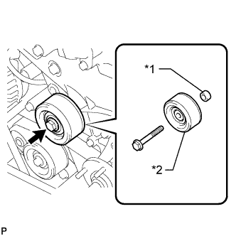 |
Install the spacer and pulley with the bolt.
- Torque:
- 43 N*m{438 kgf*cm, 32 ft.*lbf}
Text in Illustration *1 Spacer *2 Pulley
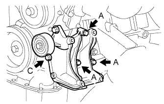
| 7. INSTALL NO. 1 COMPRESSOR MOUNTING BRACKET (w/ Air Conditioning System) |
- NOTICE:
- In order to prevent misalignment, which causes belt rattle, the 5 bolts must be tightened exactly as described in the procedures below.
Temporarily install the mounting bracket with the 3 bolts labeled A.
Text in Illustration *1 Bolt B *2 Mounting Bracket *a Engine Front *b No Clearance - HINT:
- Make sure the flanges of the bolts are contacting the bracket surface.
 |
Make sure there is no clearance between the cylinder block and bracket as shown in the illustration. Then install the bolt labeled B.
- Torque:
- for bolt B:
- 45 N*m{459 kgf*cm, 33 ft.*lbf}
Tighten the bolts labeled A and install the bolt labeled C.
- Torque:
- for bolt A:
- 45 N*m{459 kgf*cm, 33 ft.*lbf}
- for bolt C:
- 25 N*m{250 kgf*cm, 18 ft.*lbf}
 |
| 8. INSTALL EXHAUST MANIFOLD |
Install a new gasket.
Install the exhaust manifold with 8 new nuts, and tighten the nuts in the order shown in the illustration.
- Torque:
- 36 N*m{367 kgf*cm, 27 ft.*lbf}
 |
| 9. INSTALL AIR SWITCHING VALVE ASSEMBLY |
Install the air switching valve assembly with 2 new nuts.
- Torque:
- 20 N*m{204 kgf*cm, 15 ft.*lbf}
Connect the air switching valve connector.
| 10. INSTALL NO. 4 INTAKE PIPE |
Install 2 new gaskets and the No. 4 intake pipe with 4 new nuts and tighten the nuts in the order shown in the illustration. Then, tighten the nuts labeled 1 and 3 to the torque specification again.
- Torque:
- 20 N*m{204 kgf*cm, 15 ft.*lbf}
 |
Check that the nuts are tightened to the torque specification.
| 11. INSTALL NO. 1 EXHAUST MANIFOLD HEAT INSULATOR |
Install the heat insulator with the 5 bolts.
- Torque:
- 12 N*m{122 kgf*cm, 9 ft.*lbf}
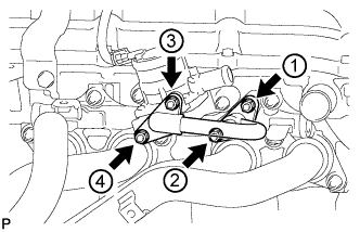
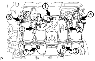
| 12. INSTALL INTAKE MANIFOLD |
Install a new gasket.
Install the intake manifold with the 5 bolts and 2 nuts and tighten the bolts and nuts in the order shown in the illustration.
- Torque:
- 25 N*m{255 kgf*cm, 18 ft.*lbf}
 |
Connect the crankshaft position sensor to the clamp.
| 13. INSTALL PURGE VSV |
Install the bracket with the bolt.
- Torque:
- 10 N*m{102 kgf*cm, 7 ft.*lbf}
Install the purge VSV together with the bracket with the bolt.
- Torque:
- 10 N*m{102 kgf*cm, 7 ft.*lbf}
Text in Illustration *a Front *b Top
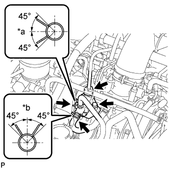 |
Connect the 2 purge line hoses to the purge VSV.
Connect the purge VSV connector.
| 14. INSTALL FUEL DELIVERY PIPE WITH FUEL INJECTOR |
Apply a light coat of gasoline or spindle oil to new O-rings, and then install one to each spacer.
Install the 4 spacers to the cylinder head.
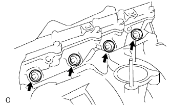 |
Install 4 new injector vibration insulators to the cylinder head.
Install the 2 No. 1 delivery pipe spacers to the cylinder head.
Install the fuel delivery pipe together with the 4 fuel injectors with the 2 bolts.
- Torque:
- 12 N*m{122 kgf*cm, 9 ft.*lbf}
- NOTICE:
- Do not drop the fuel injectors when installing the fuel delivery pipe.
Connect the 4 injector connectors.
Connect the 4 clamps and wire harness to the delivery pipe.
Connect the vacuum hose.
| 15. INSTALL THROTTLE BODY WITH MOTOR ASSEMBLY |
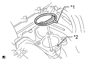
Install a new gasket on the intake manifold.
Text in Illustration *1 Protrusion *2 Groove - HINT:
- Align the protrusion of the gasket with the groove of the intake manifold.
 |
Install the throttle body with motor the 2 bolts and 2 nuts.
- Torque:
- 9.0 N*m{92 kgf*cm, 80 in.*lbf}
Connect the 2 water by-pass hoses to the throttle body with motor.
Connect the throttle position sensor and control motor connector.
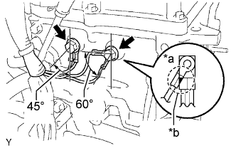
| 16. INSTALL ENGINE WIRE |
Connect the wire harness (engine ground wire) to the rear side of the engine with the 2 bolts so that it is within the specified range shown in the illustration.
- Torque:
- 31 N*m{316 kgf*cm, 23 ft.*lbf}
Text in Illustration *a INCORRECT *b Do not Allow Wires to Overlap
 |
Connect the oil pressure switch connector.
Connect the noise filter connector.
Connect the camshaft position sensor connector.
Connect the 4 injector connectors.
Connect the crankshaft position sensor connector.
Connect the camshaft timing oil control valve connector.
Connect the purge VSV connector.
Connect the throttle body connector.
Connect the engine coolant temperature sensor connector.
Connect the knock sensor connector.
Connect the wire harness to the clamps.
| 17. INSTALL GENERATOR ASSEMBLY |
Install the generator with the 2 bolts.
- Torque:
- 43 N*m{438 kgf*cm, 32 ft.*lbf}
Connect the generator connector.
Install the generator wire with the bolt and nut.
- Torque:
- for nut:
- 9.8 N*m{100 kgf*cm, 87 in.*lbf}
- for bolt:
- 13 N*m{133 kgf*cm, 10 ft.*lbf}
Attach the terminal cap.
| 18. INSTALL PCV PIPE |
Install the PCV pipe with the bolt.
- Torque:
- 18 N*m{184 kgf*cm, 13 ft.*lbf}
Connect the PCV hose to the PCV valve sub-assembly and intake manifold.
| 19. INSTALL IGNITION COIL ASSEMBLY |
Install the 4 ignition coils with the 4 bolts.
- Torque:
- 9.0 N*m{92 kgf*cm, 80 in.*lbf}
Connect the ignition coil connector.