Cylinder Block (W/ Glow Plug Controller) -- Inspection |
| 1. INSPECT CYLINDER BLOCK OIL ORIFICE |
Check the oil orifice for damage or clogging.
If necessary, replace the cylinder block oil orifice.
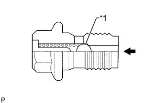
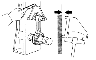
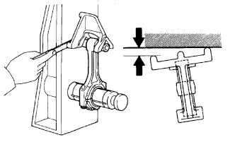
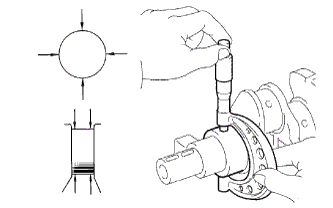
| 2. INSPECT OIL CHECK VALVE SUB-ASSEMBLY |
Push the ball of the oil check valve with a wooden stick to check if it is stuck.
If the ball of the oil check valve is stuck, replace the oil check valve sub-assembly.Text in Illustration *1 Ball 
Push
 |
| 3. INSPECT NO. 1 OIL NOZZLE SUB-ASSEMBLY |
Check the No. 1 oil nozzle for damage or clogging.
If necessary, replace the No. 1 oil nozzle sub-assembly.
| 4. CLEAN CYLINDER BLOCK SUB-ASSEMBLY |
Using a gasket scraper, remove all the gasket material from the top surface of the cylinder block.
Using a soft brush and solvent, thoroughly clean the cylinder block sub-assembly.
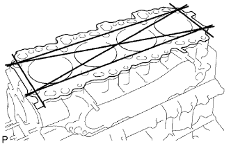
| 5. INSPECT CYLINDER BLOCK FOR WARPAGE |
Inspect for warpage.
Using a precision straightedge and feeler gauge, measure the surface of the cylinder block that contacts the cylinder head for warpage.
- Maximum warpage:
- 0.1 mm (0.00394 in.)
 |
Visually check the cylinders for vertical scratches.
If deep scratches are present, rebore all 4 cylinders. If necessary, replace the cylinder block.
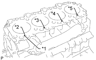
| 6. INSPECT CYLINDER BORE |
Inspect the cylinder bore diameter.
Text in Illustration *1 Mark 1, 2 or 3 *2 No. 1 *3 No. 2 *4 No. 3 *5 No. 4 - HINT:
- There are 3 standard cylinder bore diameter sizes, marked 1, 2 and 3 accordingly. The mark is stamped on the cylinder block.
Using a cylinder gauge, measure the cylinder bore diameter at positions A, B and C in the thrust and axial directions.
- Standard Diameter:
Item Specified Condition STD Mark 1 96.00 to 96.01 mm (3.7795 to 3.7799 in.) STD Mark 2 96.01 to 96.02 mm (3.7799 to 3.7803 in.) STD Mark 3 96.02 to 96.03 mm (3.7803 to 3.7807 in.) O/S 0.50 96.50 to 96.53 mm (3.7992 to 3.8004 in.) O/S 0.75 96.75 to 96.78 mm (3.8090 to 3.8102 in.) O/S 1.00 97.00 to 97.03 mm (3.8189 to 3.8201 in.)
- Maximum Diameter:
Item Specified Condition STD 96.23 mm (3.7886 in.) O/S 0.50 96.73 mm (3.8083 in.) O/S 0.75 96.98 mm (3.8181 in.) O/S 1.00 97.23 mm (3.8279 in.)
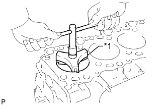
If the diameter is more than the maximum, rebore all 4 cylinders. If necessary, replace the cylinder block sub-assembly.Text in Illustration *1 Axial Direction *2 Thrust Direction *3 Center Front
If the wear is less than 0.2 mm (0.0078 in.), using a ridge reamer, grind the top of the cylinder.Text in Illustration *1 Ridge Reamer

 |
| 7. CLEAN PISTON |
Using a groove cleaning tool or broken ring, clean the piston ring grooves.
Using solvent and a brush, thoroughly clean the piston.
- NOTICE:
- Do not use a wire brush.
| 8. INSPECT PISTON WITH PIN SUB-ASSEMBLY |
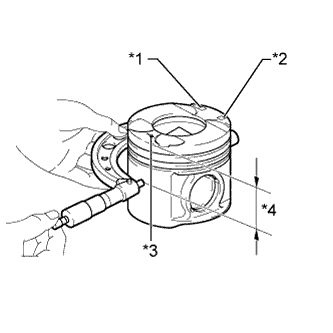
Using a micrometer, measure the piston diameter according to the following conditions: 1) measure at a right angle to the piston center line, and 2) measure at the indicated distance from the piston head.
- Distance:
- 63.5 mm (2.50 in.)
- Standard Piston Diameter:
Item Specified Condition STD Mark 1 95.92 to 95.93 mm (3.7764 to 3.7768 in.) STD Mark 2 95.93 to 95.94 mm (3.7768 to 3.7772 in.) STD Mark 3 95.94 to 95.95 mm (3.7772 to 3.7776 in.) O/S 0.50 96.42 to 96.45 mm (3.7960 to 3.7972 in.) O/S 0.75 96.67 to 96.70 mm (3.8059 to 3.8070 in.) O/S 1.00 96.92 to 96.95 mm (3.8157 to 3.8169 in.)
- Standard Pin Hole Inside Diameter:
Item Specified Condition Mark A 34.011 to 34.015 mm (1.3390 to 1.3392 in.) Mark B 34.015 to 34.019 mm (1.3392 to 1.3393 in.) Mark C 34.019 to 34.023 mm (1.3393 to 1.3395 in.)
Text in Illustration *1 Size Mark *2 Piston Pin Hole Inside Diameter Mark *3 Front Mark (Arrow) *4 Distance
 |
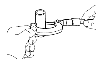
Using a micrometer, measure the piston pin diameter.
- Standard Piston Pin Diameter:
Item Specified Condition Mark A 34.000 to 34.004 mm (1.3386 to 1.3387 in.) Mark B 34.004 to 34.008 mm (1.3387 to 1.3389 in.) Mark C 34.008 to 34.012 mm (1.3389 to 1.3391 in.)
 |
Subtract the piston pin diameter measurement from the piston pin hole inside diameter measurement.
- Standard oil clearance:
- 0.007 to 0.015 mm (0.000276 to 0.000591 in.)
Inspect the piston pin fit.
At 80°C (176°F), check that the piston pin can be pushed into the piston pin hole with your thumb.
If the pin can be installed at a lower temperature, replace the piston with pin sub-assembly.
 |
| 9. INSPECT PISTON OIL CLEARANCE |
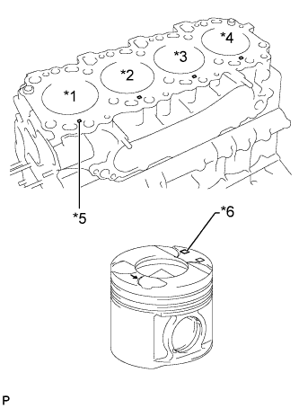
Measure the cylinder bore diameter in the thrust direction.
Text in Illustration *1 No. 1 *2 No. 2 *3 No. 3 *4 No. 4 *5 Mark 1, 2 or 3 *6 Size Mark
 |
Subtract the piston diameter measurement from the cylinder bore diameter measurement.
- Standard oil clearance:
- 0.07 to 0.09 mm (0.00276 to 0.00354 in.)
- Maximum oil clearance:
- 0.14 mm (0.00551 in.)
If necessary, replace the cylinder block sub-assembly.- HINT:
- When the cylinder block is replaced, use a piston with the same number mark as the cylinder diameter marked on a new cylinder block.
| 10. INSPECT RING GROOVE CLEARANCE |
Using a feeler gauge, measure the clearance between a new piston ring and the wall of the ring groove.
- Standard Groove Clearance:
Item Specified Condition No. 1 piston ring 0.091 to 0.135 mm (0.00358 to 0.00531 in.) No. 2 piston ring 0.090 to 0.135 mm (0.00354 to 0.00531 in.) Oil ring 0.030 to 0.075 mm (0.00118 to 0.00295 in.)
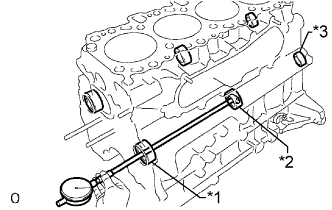
| 11. INSPECT PISTON RING END GAP |
Insert the piston ring into the cylinder bore.
Using a piston, push the piston ring a little beyond the bottom of the ring travel, 120 mm (4.72 in.) from the top of the cylinder block.
Using a feeler gauge, measure the end gap.
- Standard End Gap:
Item Specified Condition No. 1 piston ring 0.27 to 0.39 mm (0.0106 to 0.0154 in.) No. 2 piston ring 0.55 to 0.70 mm (0.0217 to 0.0276 in.) Oil ring 0.20 to 0.40 mm (0.00787 to 0.0157 in.)
- Maximum End Gap:
Item Specified Condition No. 1 piston ring 0.85 mm (0.0335 in.) No. 2 piston ring 1.07 mm (0.0421 in.) Oil ring 0.77 mm (0.0303 in.)
If the end gap is more than the maximum even with a new piston ring, rebore all 4 cylinders or replace the cylinder block sub-assembly.
| 12. INSPECT PISTON PIN OIL CLEARANCE |
Using a caliper gauge, measure the inside diameter of the connecting rod bush.
- Standard Bush Inside Diameter:
Item Specified Condition Mark A 34.012 to 34.016 mm (1.3390 to 1.3392 in.) Mark B 34.016 to 34.020 mm (1.3392 to 1.3394 in.) Mark C 34.020 to 34.024 mm (1.3394 to 1.3395 in.)
Text in Illustration *1 Connecting Rod Bush Inside Diameter Mark A, B or C *2 Front Mark
 |
Subtract the piston pin diameter measurement from the bush inside diameter measurement.
- Standard oil clearance:
- 0.008 to 0.016 mm (0.000315 to 0.000630 in.)
- Maximum oil clearance:
- 0.03 mm (0.0118 in.)
If necessary, replace the piston with pin sub-assembly.
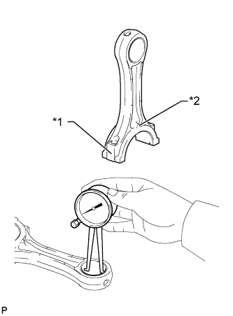
| 13. INSPECT CONNECTING ROD SUB-ASSEMBLY |
Using a rod aligner and feeler gauge, check the connecting rod alignment.
Check if the connecting rod is bent.
- Maximum bend:
- 0.03 mm (0.00118 in.) per 100 mm (3.94 in.)
Check if the connecting rod is twisted.
- Maximum twist:
- 0.15 mm (0.00591 in.) per 100 mm (3.94 in.)
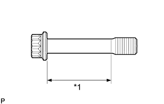
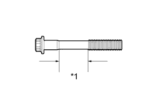
| 14. INSPECT CONNECTING ROD BOLT |
Using a vernier caliper, measure the diameter of the tension portion of the bolt.
- Standard diameter:
- 8.5 to 8.6 mm (0.335 to 0.339 in.)
- Minimum diameter:
- 8.3 mm (0.327 in.)
If the diameter is less than the minimum, replace the connecting rod bolt.Text in Illustration *1 Tension Portion
 |
| 15. INSPECT NO. 1 BALANCESHAFT SUB-ASSEMBLY |
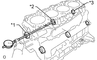 |
Using a cylinder gauge, measure the inside diameter of the balanceshaft bearing.
- Standard Bearing Inside Diameter:
Item Specified Condition No. 1 42.000 to 42.020 mm (1.6535 to 1.6543 in.) No. 2 41.000 to 41.020 mm (1.6142 to 1.6150 in.) No. 3 32.000 to 32.020 mm (1.2598 to 1.2606 in.)
Text in Illustration *1 No. 1 *2 No. 2 *3 No. 3
Using a micrometer, measure the outside diameter of the balanceshaft main journals.
- Standard Main Journal Diameter:
Item Specified Condition No. 1 41.941 to 41.960 mm (1.6512 to 1.6520 in.) No. 2 40.931 to 40.950 mm (1.6115 to 1.6122 in.) No. 3 31.941 to 31.960 mm (1.2575 to 1.2583 in.)
 |
Subtract the outside diameter of the balanceshaft main journal from the inside diameter of the balanceshaft bearing.
- Standard Oil Clearance:
Item Specified Condition No. 1 0.040 to 0.079 mm (0.00157 to 0.00311 in.) No. 2 0.050 to 0.089 mm (0.00197 to 0.00350 in.) No. 3 0.040 to 0.079 mm (0.00157 to 0.00311 in.)
- Maximum Oil Clearance:
Item Specified Condition No. 1 0.18 mm (0.00709 in.) No. 2 0.19 mm (0.00748 in.) No. 3 0.18 mm (0.00709 in.)
| 16. INSPECT NO. 2 BALANCESHAFT SUB-ASSEMBLY |
Using a cylinder gauge, measure the inside diameter of the balanceshaft bearing.
- Standard Bearing Inside Diameter:
Item Specified Condition No. 1 42.000 to 42.020 mm (1.6535 to 1.6543 in.) No. 2 41.000 to 41.020 mm (1.6142 to 1.6150 in.) No. 3 32.000 to 32.020 mm (1.2598 to 1.2606 in.)
Text in Illustration *1 No. 1 *2 No. 2 *3 No. 3
 |
Using a micrometer, measure the outside diameter of the balanceshaft main journals.
- Standard Main Journal Diameter:
Item Specified Condition No. 1 41.941 to 41.960 mm (1.6512 to 1.6520 in.) No. 2 40.931 to 40.950 mm (1.6115 to 1.6122 in.) No. 3 31.941 to 31.960 mm (1.2575 to 1.2583 in.)
|
Subtract the outside diameter of the balanceshaft main journal from the inside diameter of the balanceshaft bearing.
- Standard Oil Clearance:
Item Specified Condition No. 1 0.040 to 0.079 mm (0.00157 to 0.00311 in.) No. 2 0.050 to 0.089 mm (0.00197 to 0.00350 in.) No. 3 0.040 to 0.079 mm (0.00157 to 0.00311 in.)
- Maximum Oil Clearance:
Item Specified Condition No. 1 0.18 mm (0.00709 in.) No. 2 0.19 mm (0.00748 in.) No. 3 0.18 mm (0.00709 in.)
| 17. INSPECT CRANKSHAFT |
Inspect for circle runout.
Place the crankshaft on V-blocks.
Using a dial indicator, measure the circle runout at the center journal.
- Maximum circle runout:
- 0.03 mm (0.00118 in.)
Inspect the main journals and crank pins.
Using a micrometer, measure the diameter of each main journal and crank pin.
- Standard Main Journal Diameter:
Item Specified Condition Mark 1 69.994 to 70.000 mm (2.7557 to 2.7559 in.) Mark 2 69.988 to 69.994 mm (2.7554 to 2.7557 in.) Mark 3 69.982 to 69.988 mm (2.7552 to 2.7554 in.) U/S 0.25 69.745 to 69.755 mm (2.7459 to 2.7463 in.) U/S 0.50 69.495 to 69.505 mm (2.7360 to 2.7364 in.)
- Standard Crank Pin Diameter:
Item Specified Condition Mark 1 58.994 to 59.000 mm (2.3226 to 2.3228 in.) Mark 2 58.988 to 58.994 mm (2.3224 to 2.3226 in.) Mark 3 58.982 to 58.988 mm (2.3221 to 2.3224 in.)
Check each main journal and crank pin for taper and out-of-round as shown in the illustration.
- Maximum taper and out-of-round:
- 0.02 mm (0.000787 in.)
 |
If necessary, grind and hone the main journals and/or crank pins.
Grind and hone the main journals and/or crank pins to the finished undersized diameter (refer to the procedures above).
Install new main journal and/or crank pin undersized bearings.
| 18. INSPECT CRANKSHAFT BEARING CAP SET BOLT |
Using a vernier caliper, measure the diameter of the crankshaft bearing cap set bolt in the measuring area.
- Standard diameter:
- 13.5 to 14.0 mm (0.531 to 0.551 in.)
- Minimum diameter:
- 12.6 mm (0.496 in.)
If the diameter is less than the minimum, replace the crankshaft bearing cap set bolt.Text in Illustration *1 Measuring Area
 |