DESCRIPTION
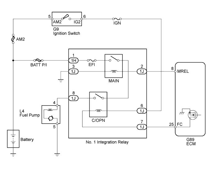
WIRING DIAGRAM
INSPECTION PROCEDURE
PERFORM ACTIVE TEST USING INTELLIGENT TESTER (CONTROL THE FUEL PUMP / SPEED)
READ VALUE USING INTELLIGENT TESTER (STARTER SIGNAL)
READ VALUE USING INTELLIGENT TESTER (ENGINE SPEED)
CHECK HARNESS AND CONNECTOR (NO. 1 INTEGRATION RELAY - ECM)
INSPECT NO. 1 INTEGRATION RELAY (C/OPN RELAY INPUT VOLTAGE)
CHECK HARNESS AND CONNECTOR (NO. 1 INTEGRATION RELAY - FUEL PUMP - BODY GROUND)
INSPECT FUEL PUMP
INSPECT NO. 1 INTEGRATION RELAY (C/OPN)
CHECK HARNESS AND CONNECTOR (IGNITION SWITCH - NO. 1 INTEGRATION RELAY)
SFI SYSTEM (w/ Secondary Air Injection System) - Fuel Pump Control Circuit |
DESCRIPTION
When the engine is cranked, the starter (ST) relay drive signal output from the ignition switch is input into the STA terminal of the ECM, and the NE signal generated by the crankshaft position sensor is input into the NE+ terminal. The ECM determines that the engine is cranked, and turns transistor in the ECM internal circuit on. Current flows to the circuit opening (C/OPN) relay by turning transistor on.Then, the fuel pump operates.While the NE signal is input into the ECM and the engine is running, the ECM turns transistor on continuously.
WIRING DIAGRAM
INSPECTION PROCEDURE
- NOTICE:
- Inspect the fuses of circuits related to this system before performing the following inspection procedure.
| 1.PERFORM ACTIVE TEST USING INTELLIGENT TESTER (CONTROL THE FUEL PUMP / SPEED) |
Connect the intelligent tester to the DLC3.
Turn the ignition switch to ON and turn the intelligent tester on.
Enter the following menus: Powertrain / Engine and ECT / Active Test / Control the Fuel Pump / Speed.
Check whether the fuel pump operating sound occurs when performing the Active Test on the intelligent tester.
- OK:
- Fuel pump operating sound occurs.
| 2.READ VALUE USING INTELLIGENT TESTER (STARTER SIGNAL) |
Connect the intelligent tester to the DLC3.
Turn the ignition switch to ON and turn the intelligent tester on.
Enter the following menus: Powertrain / Engine and ECT / Data List / Starter Signal.
Check the result when the ignition switch is turned to ON and START.
- OK:
Ignition Switch Position
| Starter Signal
|
ON
| Close (Starter signal OFF)
|
START
| Open (Starter signal ON)
|
| | REPAIR OR REPLACE STARTING SYSTEM |
|
|
| 3.READ VALUE USING INTELLIGENT TESTER (ENGINE SPEED) |
Connect the intelligent tester to the DLC3.
Turn the ignition switch to ON and turn the intelligent tester on.
Enter the following menus: Powertrain / Engine and ECT / Data List / Engine Speed.
Read the values displayed on the intelligent tester while cranking the engine.
- OK:
- Values are displayed continuously.
| | REPAIR OR REPLACE CRANKSHAFT POSITION SENSOR CIRCUIT |
|
|
| 4.CHECK HARNESS AND CONNECTOR (NO. 1 INTEGRATION RELAY - ECM) |
Disconnect the ECM connector.
Disconnect the No. 1 integration relay connector.
Measure the resistance according to the value(s) in the table below.
- Standard Resistance:
Tester Connection
| Condition
| Specified Condition
|
G89-25 (FC) - 1J-7
| Always
| Below 1 Ω
|
G89-25 (FC) or 1J-7 - Body ground
| Always
| 10 kΩ or higher
|
| | REPAIR OR REPLACE HARNESS OR CONNECTOR |
|
|
| 5.INSPECT NO. 1 INTEGRATION RELAY (C/OPN RELAY INPUT VOLTAGE) |
Remove the No. 1 integration relay from the engine room relay block and junction block.
Measure the voltage according to the value(s) in the table below.
- Standard Voltage:
Tester Connection
| Switch Condition
| Specified Condition
|
1J-6 - Body ground
| Ignition switch off
| Below 1 V
|
1J-8 - Body ground
|
1J-6 - Body ground
| Ignition switch ON
| 11 to 14 V
|
1J-8 - Body ground
| Engine cranking
|
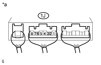
Text in Illustration*a
| Component with harness connected
(No. 1 Integration Relay)
|
| 6.CHECK HARNESS AND CONNECTOR (NO. 1 INTEGRATION RELAY - FUEL PUMP - BODY GROUND) |
Check the harness and connectors between the No. 1 integration relay and fuel pump.
Remove the No. 1 integration relay from the engine room relay block and junction block.
Disconnect the fuel pump connector.
Measure the resistance according to the value(s) in the table below.
- Standard Resistance:
Tester Connection
| Condition
| Specified Condition
|
L4-4 - 1J-8
| Always
| Below 1 Ω
|
L4-4 or 1J-8 - Body ground
| Always
| 10 kΩ or higher
|
Check the harness and connectors between the fuel pump and body ground.
Disconnect the fuel pump connector.
Measure the resistance according to the value(s) in the table below.
- Standard Resistance:
Tester Connection
| Condition
| Specified Condition
|
L4-5 - Body ground
| Always
| Below 1 Ω
|
| | REPAIR OR REPLACE HARNESS OR CONNECTOR |
|
|
Inspect the fuel pump (HILUX_TGN26 RM000000YLJ01MX_01_0001.html).
| 8.INSPECT NO. 1 INTEGRATION RELAY (C/OPN) |
Inspect the No. 1 integration relay (C/OPN) (HILUX_TGN26 RM000003BLB021X_01_0018.html).
| | REPLACE NO. 1 INTEGRATION RELAY |
|
|
| 9.CHECK HARNESS AND CONNECTOR (IGNITION SWITCH - NO. 1 INTEGRATION RELAY) |
Remove the No. 1 integration relay from the engine room relay block and junction block.
Disconnect the ignition switch connector.
Measure the resistance according to the value(s) in the table below.
- Standard Resistance:
Tester Connection
| Condition
| Specified Condition
|
G9-6 (IG2) - 1J-6
| Always
| Below 1 Ω
|
G9-6 (IG2) or 1J-6 - Body ground
| Always
| 10 kΩ or higher
|
| | REPAIR OR REPLACE HARNESS OR CONNECTOR |
|
|