INSTALL FRONT BUMPER ENERGY ABSORBER LH (w/ Energy Absorber)
INSTALL FRONT BUMPER ENERGY ABSORBER RH (w/ Energy Absorber)
PREPARE VEHICLE FOR FOG LIGHT AIMING ADJUSTMENT (w/ Fog Light)
Front Bumper (For Sedan) -- Installation |
| 1. INSTALL FRONT BUMPER ARM SUB-ASSEMBLY LH |
Insert the 2 locating pins into the 2 body holes and install the front bumper arm with the 4 bolts.
- Torque:
- 40 N*m{410 kgf*cm, 30 ft.*lbf}
 |
| 2. INSTALL FRONT BUMPER ARM SUB-ASSEMBLY RH |
- HINT:
- Use the same procedure as for the LH side.
| 3. INSTALL WINDSHIELD WASHER JAR ASSEMBLY |
Insert the location pin into the body hole and install the windshield washer jar with the 2 bolts.
- Torque:
- 5.5 N*m{55 kgf*cm, 49 in.*lbf}
 |
| 4. INSTALL HEADLIGHT ASSEMBLY RH |
- HINT:
- Use the same procedure as for the LH side (YARIS_NCP93 RM000000RJR01EX_01_0001.html).
| 5. INSTALL FRONT BUMPER STONE DEFLECTOR BRACKET |
Install the front bumper stone deflector bracket with the 2 nuts.
- Torque:
- 5.5 N*m{55 kgf*cm, 49 in.*lbf}
- HINT:
- Use the same procedure as for the opposite side.
 |
| 6. INSTALL FRONT BUMPER REINFORCEMENT SUB-ASSEMBLY |
Install the front bumper reinforcement with the 6 bolts and 4 nuts.
- Torque:
- 40 N*m{410 kgf*cm, 30 ft.*lbf}for bolt
- 5.5 N*m{55 kgf*cm, 49 in.*lbf}for nut
 |
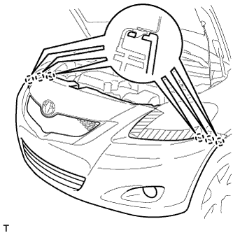
| 7. CONNECT NO. 2 ENGINE ROOM WIRE (w/ Fog Light) |
Install the No. 2 engine room wire with the 7 clamps.
 |
| 8. CONNECT NO. 2 ENGINE ROOM WIRE (w/o Fog Light) |
Install the No. 2 engine room wire with the 6 clamps.
 |
| 9. INSTALL RADIATOR SUPPORT EXTENSION LH (w/ Energy Absorber) |
Engage the 2 claws and install the radiator support extension.
 |
| 10. INSTALL RADIATOR SUPPORT EXTENSION RH (w/ Energy Absorber) |
- HINT:
- Use the same procedure as for the LH side.
| 11. INSTALL RADIATOR SIDE AIR SEAL LH (w/ Energy Absorber) |
Engage the 2 claws and install the radiator side air seal.
 |
| 12. INSTALL RADIATOR SIDE AIR SEAL RH (w/ Energy Absorber) |
- HINT:
- Use the same procedure as for the LH side.
| 13. INSTALL RADIATOR SIDE AIR SEAL LH (w/o Energy Absorber) |
Engage the 4 claws and install the radiator side air seal.
 |
| 14. INSTALL RADIATOR SIDE AIR SEAL RH (w/o Energy Absorber) |
- HINT:
- Use the same procedure as for the LH side.
| 15. INSTALL THERMISTOR ASSEMBLY (w/ Air Conditioning System) |
Install the thermistor with the 2 clamps.
 |
| 16. INSTALL RADIATOR SUPPORT UPPER ABSORBER |
Engage the 6 claws and install the radiator support absorber.
 |
| 17. INSTALL FRONT BUMPER ENERGY ABSORBER LH (w/ Energy Absorber) |
Insert the 2 bosses into the hole of the front bumper reinforcement and install the front bumper energy absorber.
 |
| 18. INSTALL FRONT BUMPER ENERGY ABSORBER RH (w/ Energy Absorber) |
- HINT:
- Use the same procedure as for the LH side.
| 19. INSTALL FRONT BUMPER SIDE RETAINER LH |
Engage the 2 claws and install the front bumper side retainer.
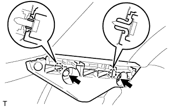 |
Tighten the screw and the bolt.
- Torque:
- 5.0 N*m{51 kgf*cm, 44 in.*lbf}for bolt
| 20. INSTALL FRONT BUMPER SIDE RETAINER RH |
- HINT:
- Use the same procedure as for the LH side.
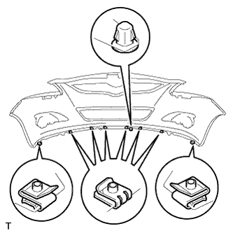
| 21. INSTALL FRONT BUMPER COVER (w/ Large Front Spoiler) |
Install the 2 clips, screw grommet and the 6 spring nuts.
 |
Engage the 6 claws and install the front bumper cover.
 |
Connect the connectors.
- HINT:
- If the vehicle is equipped with fog lights, connect the connector.
Install the 6 clips.
 |
Install the 2 screw grommets.
Tighten the 9 bolts and the 7 screws.
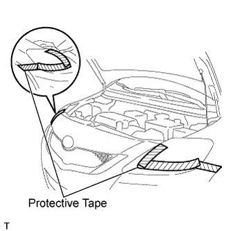
Remove the protective tape.
 |
| 22. INSTALL FRONT BUMPER COVER (w/ Small Front Spoiler) |
Install the 2 clips, the screw grommet and the 10 spring nuts.
 |
Engage the 6 claws and install the front bumper cover.
|
Connect the connectors.
- HINT:
- If the vehicle is equipped with fog lights, connect the connectors.
Install the 6 clips.
 |
Install the 2 screw grommets.
Tighten the 5 screws and the 3 bolts.
Remove the protective tape.
|
| 23. INSTALL FRONT BUMPER COVER (w/o Front Spoiler) |
Install the 2 clips and the screw grommet.
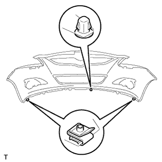 |
Engage the 6 claws and install the front bumper cover.
|
Connect the connectors.
- HINT:
- If the vehicle is equipped with fog lights, connect the connectors.
Install the 6 clips.
 |
Install the 2 screw grommets.
Tighten the 7 screws and the 3 bolts.
Remove the protective tape.
|
| 24. INSTALL FRONT SPOILER COVER (w/ Small Front Spoiler) |
Install the front spoiler cover with the 2 screws and the 10 bolts.
 |
| 25. PREPARE VEHICLE FOR HEADLIGHT AIMING ADJUSTMENT |
Prepare the vehicle:
- Ensure that there is no damage or deformation of the body around the headlights.
- Fill the fuel tank.
- Fill the oil to the specified level.
- Fill the coolant to the specified level.
- Inflate the tires to the appropriate pressure.
- Place the spare tire, tools and jack in their original positions.
- Unload the trunk.
- Sit a person of average weight (68 kg, 150 lb) in the driver seat.
- Ensure that there is no damage or deformation of the body around the headlights.
| 26. PREPARE FOR HEADLIGHT AIMING (for Using a Tester) |
Prepare the vehicle for headlight aim check.
Adjust in accordance with headlight tester instructions.
| 27. PREPARE FOR HEADLIGHT AIMING (for Using a Screen) |
 |
Prepare the following vehicle conditions:
- Place the vehicle in a location that is dark enough to clearly observe the cutoff line. The cutoff line is a distinct line, below which light from the headlights can be observed and above which it cannot.
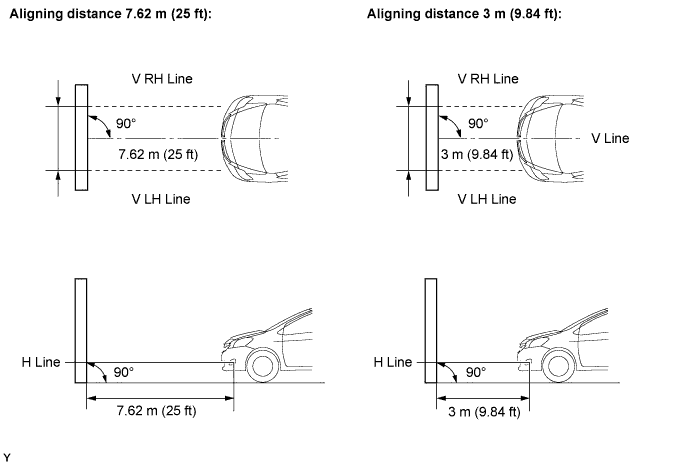
- Place the vehicle at a 90° angle to the wall.
- Keep a 7.62 m (25 ft) distance between the center of the headlight bulb and the wall.
- Place the vehicle on a level surface.
- Bounce the vehicle up and down to settle the suspension.
- NOTICE:
- A distance of 7.62 m (25 ft) between the vehicle (the center of the headlight bulb) and the wall is necessary for proper aim adjustment. If unable to secure a distance of 7.62 m (25 ft), set a distance of exactly 3 m (9.84 ft) to check and adjust the headlight aim. (Since the target zone changes depending on the distance, follow the instructions shown in the illustration.)
- Place the vehicle in a location that is dark enough to clearly observe the cutoff line. The cutoff line is a distinct line, below which light from the headlights can be observed and above which it cannot.
Prepare a piece of thick white paper (approximately 2 m (6.6 ft) high x 4 m (13.1 ft) wide) to use as a screen.
Draw a vertical line down the center of the screen (V line).
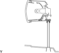
Set the screen, as shown in the illustration.

- HINT:
- Stand the screen perpendicular to the ground.
- Align the V line on the screen with the center of the vehicle.
Draw base lines (H line, V LH and V RH lines) on the screen, as shown in the illustration.
- HINT:
- The base lines differ for "low-beam inspection" and "high-beam inspection".
- Mark the headlight bulb center marks on the screen. If the center mark cannot be observed on the headlight, use the center of the headlight bulb.
H Line (Headlight height):
Draw a horizontal line across the screen so that it passes through the center marks. The H line should be at the same height as the headlight bulb center marks of the low-beam headlights.V LH Line and V RH Line (Center mark positions of left-hand (LH) and right-hand (RH) headlights):
Draw two vertical lines so that they intersect the H line at each center mark (aligned with the center of the low-beam headlight bulbs).
 |
| 28. INSPECT HEADLIGHT AIMING |
Cover the headlight on the opposite side or disconnect its connector, to prevent light from the headlight not being inspected from affecting the headlight aiming inspection.
- NOTICE:
- Do not keep the headlight covered for more than 3 minutes. The headlight lens is made of synthetic resin, and may easily melt or be damaged due to heat.
Start the engine.
- NOTICE:
- Engine rpm must be 1,500 or more.
Turn on the headlight and make sure that the cutoff line falls within the specified area, as shown in the illustration.

- HINT:
- Since the low-beam light and the high-beam light are a unit, if the aim on one is correct, the other should also be correct. However, check both beams just to make sure.
- Alignment distance is 7.62 m (25 ft):
The cutoff line is 101 mm (3.97 in.) above and below the H line as well as to the left and right of the V line with low-beam (SAE J599). - Alignment distance is 3 m (9.84 ft):
The cutoff line is 40 mm (1.57 in.) above and below the H line as well as to the left and right of the V line with low-beam (SAE J599). - Alignment distance is 7.62 m (25 ft):
The cutoff line is 101 mm (3.97 in.) above and below the H line as well as to the left and right of the V line with high-beam (SAE J599). - Alignment distance is 3 m (9.84 ft):
The cutoff line is 40 mm (1.57 in.) above and below the H line as well as to the left and right of the V line with high-beam (SAE J599). - Alignment distance is 7.62 m (25 ft):
The cutoff line is 53 mm (2.08 in.) below the H line with low-beam. - Alignment distance is 3 m (9.84 ft):
The cutoff line is 21 mm (0.82 in.) below the H line with low-beam.
| 29. ADJUST HEADLIGHT AIMING |
Adjust the aiming vertically:
Adjust the headlight aim to within the specified range by turning aiming screw A with a screwdriver.- NOTICE:
- The final turn of the aiming screw should be made in the clockwise direction. If the screw is tightened excessively, loosen it and then retighten it, so that the final turn of the screw is in the clockwise direction.
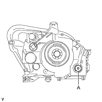 |
Perform low-beam aim adjustment.
- HINT:
- The headlight aim moves down when the aiming screw is turned clockwise, and moves up when the aiming screw is turned counterclockwise.
| 30. PREPARE VEHICLE FOR FOG LIGHT AIMING ADJUSTMENT (w/ Fog Light) |
Prepare the vehicle:
- Ensure that there is no damage or deformation of the body around the fog lights.
- Fill the fuel tank.
- Fill the oil to the specified level.
- Fill the coolant to the specified level.
- Inflate the tires to the appropriate pressure.
- Place the spare tire, tools and jack in their original positions.
- Unload the trunk.
- Sit a person of average weight (75 kg, 165 lb) in the driver seat.
- Ensure that there is no damage or deformation of the body around the fog lights.
| 31. PREPARE FOR FOG LIGHT AIMING (w/ Fog Light) |
 |
Prepare the vehicle in accordance with the following conditions:
- Place the vehicle in a location that is dark enough to clearly observe the cutoff line. The cutoff line is a distinct line, below which light from the fog lights can be observed and above which it cannot.
- Place the vehicle at a 90°angle to the wall.
- Keep a 7.62 m (25 ft) distance between the center of the fog light bulb and the wall.
- Place the vehicle on a level surface.
- Bounce the vehicle up and down to settle the suspension.
- NOTICE:
- A distance of 7.62 m (25 ft) between the vehicle (center of the fog light bulb) and the wall is necessary for proper aim adjustment. If unable to secure a distance of 7.62 m (25 ft), secure a distance of exactly 3 m (9.84 ft) to check and adjust the fog light aim. (Since the target zone will change with the distance, follow the instructions shown in the illustration.)
- Place the vehicle in a location that is dark enough to clearly observe the cutoff line. The cutoff line is a distinct line, below which light from the fog lights can be observed and above which it cannot.
Prepare a piece of thick white paper (approximately 2 m (6.6 ft) (high) x 4 m (13.1 ft) (wide)) to use as a screen.
Draw a vertical line down the center of the screen (V line).
Set the screen as shown in the illustration.
- HINT:
- Stand the screen perpendicular to the ground.
- Align the V line on the screen with the center of the vehicle.
Draw base lines (H line, V LH, V RH lines) on the screen as shown in the illustration.
- HINT:
- Mark the fog light bulb center marks on the screen. If the center mark cannot be observed on the fog light, use the center of the fog light bulb or the manufacturer's name marked on the fog light as the center mark.
H Line (Fog light height):
Draw a horizontal line across the screen so that it passes through the center marks. The H line should be at the same height as the fog light bulb center marks of the low-beam fog lights.V LH Line and V RH Line (Center mark positions of left-hand (LH) and right-hand (RH) fog lights):
Draw two vertical lines so that they intersect the H line at each center mark.
|
| 32. INSPECT FOG LIGHT AIMING (w/ Fog Light) |
Cover the fog light or disconnect the connector of the fog light on the opposite side to prevent light from the fog light not being inspected from affecting fog light aiming inspection.
Start the engine.
- NOTICE:
- Engine rpm must be 1,500 or more.
Turn on the fog light and make sure that the cutoff line falls within the specified area, as shown in the illustration.

| 33. ADJUST FOG LIGHT AIMING (w/ Fog Light) |
 |
Adjust the fog light aim to within the specified range by turning the aiming screw with a screwdriver.
- NOTICE:
- The final turn of the aiming screw should be made in the clockwise direction. If the screw is tightened excessively, loosen it and then retighten it, so that the final turn of the screw is in the clockwise direction.