Air Conditioning Panel (For Sedan) -- Inspection |
| 1. INSPECT HEATER CONTROL BASE SUB-ASSEMBLY |
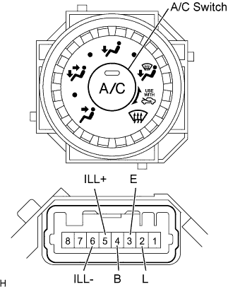 |
Check the heater control base resistance.
Using an ohmmeter, measure the resistance and check the results in accordance with the values in the table below.
- Standard resistance:
Tester Connection Condition Specified Condition 2 (L) - 3 (E) Always 10 kΩ or higher 2 (L) - 4 (B) A/C switch OFF 10 kΩ or higher 3 (E) - 4 (B) Always 10 kΩ or higher 2 (L) - 4 (B) A/C switch ON Below 1 Ω 5 (ILL+) - 6 (ILL-) Always Below 1 Ω
Check the A/C indicator operation.
Connect the positive (+) lead from the battery to terminal 2 (L) and the negative (-) lead to terminal (E).
Push the A/C switch in and check that the indicator lights up.
- Standard:
- Indicator lights up
Check the illumination operation.
Connect the positive (+) lead from the battery to terminal 5 (ILL+) and the negative (-) lead to terminal 6 (ILL-), then check that the bulb illuminates.
- Standard:
- Bulb illuminates
| 2. INSPECT HEATER CONTROL SUB-ASSEMBLY |
 |
Check the heater control resistance.
Using an ohmmeter, measure the resistance and check the results in accordance with the values in the table below.
- Standard resistance:
Switch Position Tester Connection Specified Condition OFF ALL - 5 (E) 10 kΩ or higher LO 9 (LO) - 5 (E) Below 1 Ω LO - M1 9 (LO) - 5 (E) - 7 (M1) Below 1 Ω M1 9 (LO) - 5 (E) - 7 (M1) Below 1 Ω M1 - M2 9 (LO) - 5 (E) - 7 (M1) - 6 (M2) Below 1 Ω M2 9 (LO) - 5 (E) - 6 (M2) Below 1 Ω M2 - HI 9 (LO) - 5 (E) - 6 (M2) - 10 (HI) Below 1 Ω HI 9 (LO) - 5 (E) - 10 (HI) Below 1 Ω
Check the illumination operation.
Connect the positive (+) lead from the battery to terminal 2 (ILL+) and the negative (-) lead to terminal 1 (ILL-), then check that the bulb illuminates.
- Standard:
- Bulb illuminates
| 3. INSPECT NO. 3 HEATER CONTROL KNOB |
 |
Check the No. 3 heater control knob resistance.
Using an ohmmeter, measure the resistance and check the results in accordance with the values in the table below.
- Standard resistance:
Tester Connection Condition Specified Condition 2 (RrDEF) - 1 (E) Rr. DEF switch OFF 10 kΩ or higher 2 (RrDEF) - 1 (E) Rr. DEF switch ON Below 1 Ω 3 (IG) - 6 (MAX HOT) Except MAX HOT 10 kΩ or higher 3 (IG) - 6 (MAX HOT) MAX HOT Below 1 Ω 4 (ILL-) - 5 (ILL+) Always Below 1 Ω 7 (V/B) - 8 (SG) Always Below 1 Ω
Check the Rr. DEF indicator operation.
Connect the positive (+) lead from the battery to terminal 3 (IG) and the negative (-) lead to terminal 1 (E).
Push the Rr. DEF switch in and check that the indicator lights up.
- Standard:
- Indicator lights up
Check the illumination operation.
Connect the positive (+) lead from the battery to terminal 5 (ILL+) and the negative (-) lead to terminal 4 (ILL-), then check that the bulb illuminates.
- Standard:
- Bulb illuminates