Compressor (For Hatchback) -- Installation |
| 1. INSPECT COMPRESSOR OIL |
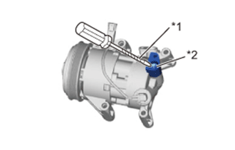
Remove the suction seal cap.
Using a screwdriver with its tip wrapped in protective tape, insert the screwdriver through the suction port and set the VST valve (valve inside suction port) to the open position.
Text in Illustration *1 Protective Tape *2 VST valve (Valve Inside Suction Port) - NOTICE:
- Be sure not to damage the piping contact surfaces with the tip of the screwdriver.
 |
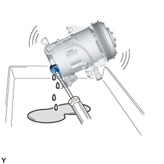
Lightly shake the compressor with the suction port facing down, and drain the oil (*1).
- NOTICE:
- Do not allow the pulley to come into contact with the compressor oil.
 |
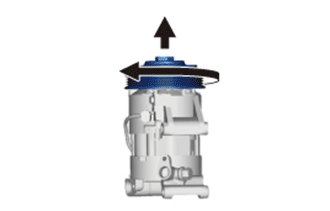
With the pulley facing down, rotate the pulley in the direction shown by the arrow 10 times at a rate of approximately once every 2 seconds (*2).
- NOTICE:
- If the pulley is rotated, refrigerant or oil might splash out. Thus, keep your face away from the compressor port.
 |
Rotate the pulley once in the direction shown by the arrow while quickly turning the compressor so the pulley is up (*3).
 |
Proceed with the above procedure (*1) and drain the oil (*4).
Drain the oil by repeating the procedures above approximately 5 times (from (*2) to (*4)).
- Standard (Amount of Oil to be Removed):
Standard (Amount of Oil to be Removed) Amount of Oil Inside a New Compressor 30 cm3 60 cm3
- HINT:
- If too much oil has been removed, set the VST valve to the open position through the suction port, and add oil.
| 2. INSTALL COMPRESSOR WITH PULLEY ASSEMBLY |
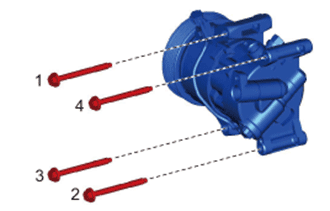
Install the compressor with the 4 bolts.
- HINT:
- Tighten the bolts in the order shown in the illustration.
- Torque:
- 25 N*m{250 kgf*cm, 18 ft.*lbf}
 |
Connect the connector.
| 3. CONNECT NO. 1 COOLER REFRIGERANT DISCHARGE HOSE |
Remove the attached vinyl tape from the discharge hose.
Apply sufficient compressor oil to a new O-ring and the fitting surface of the compressor.
- Compressor oil:
- ND-OIL 8 or equivalent
Install the O-ring onto the discharge hose.
Install the discharge hose onto the compressor with the bolt.
- Torque:
- 9.8 N*m{100 kgf*cm, 87 in.*lbf}
| 4. CONNECT SUCTION HOSE SUB-ASSEMBLY |
Remove the attached vinyl tape from the suction hose.
Apply sufficient compressor oil to a new O-ring and the fitting surface of the compressor.
- Compressor oil:
- ND-OIL 8 or equivalent
Install the O-ring onto the suction hose.
Install the suction hose onto the compressor with the bolt.
- Torque:
- 9.8 N*m{100 kgf*cm, 87 in.*lbf}
| 5. INSTALL ENGINE UNDER COVER RH |
- Torque:
- 5.0 N*m{51 kgf*cm, 44 in.*lbf}
| 6. INSTALL FAN AND GENERATOR V BELT |
| 7. CHARGE REFRIGERANT |
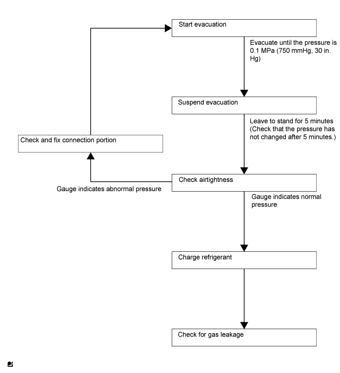
- HINT:
- Charge refrigerant in accordance with the equipment manual.
Perform vacuum purging using a vacuum pump.
Charge refrigerant HFC-134a (R134a).
- SST
- 09985-20010(09985-02010,09985-02050,09985-02060,09985-02070,09985-02080,09985-02090,09985-02110,09985-02130,09985-02140,09985-02150)
- Standard:
- 330 to 390 g (11.6 to 13.8 oz.)
- NOTICE:
- Do not start the engine before charging it with refrigerant as the cooler compressor does not work properly without sufficient refrigerant. This could cause the compressor to overheat.
- HINT:
- The relationship between the refrigerant charge amount and the pressure is as follows.
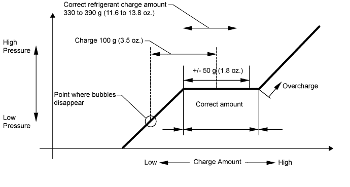
- High Charge Range:
If the refrigerant is overcharged, the pressure rises on the high-pressure side. High-pressure cut off frequently occurs. This causes insufficient cooling performance and also insufficient compressor lubrication. - Low Charge Range:
A shortage of refrigerant causes insufficient cooling performance and low circulation of refrigerant oil, which shortens the compressor life. Operation with insufficient coolant raises the refrigerant temperature and causes heat deterioration of the rubber seals and hoses. Cracking and subsequent refrigerant leakage may occur.
Install the caps onto the service valves on the refrigerant line.
| 8. WARM UP ENGINE |
- NOTICE:
- Warm up the engine at less than 2000 rpm for 1 minute or more after charging it with refrigerant.
| 9. INSPECT FOR REFRIGERANT LEAK |
After recharging the refrigerant gas, check for refrigerant gas leakage using a halogen leak detector.
Perform the operation as follows:
- Stop the engine.
- Secure good ventilation (the halogen leak detector may react to volatile gases other than refrigerant, such as evaporated gasoline or exhaust gas).
- Repeat the test 2 or 3 times.
- Make sure that some refrigerant remains in the refrigeration system.
When the compressor is off: approximately 392 to 588 kPa (4 to 6 kgf/cm2, 57 to 85 psi)
- HINT:
- It is impossible for the above pressure to be maintained if there is leakage.
- Stop the engine.
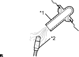
Using the halogen leak detector, check the refrigerant line, especially at the connection points, for leakage.
Text in Illustration *1 Halogen Leak Detector
 |
Bring the halogen leak detector close to the drain hose before performing the test.
Text in Illustration *1 Drain Hose *2 Halogen Leak Detector - HINT:
- After the blower motor has stopped, leave the cooling unit for at least 15 minutes.
- Place the halogen leak detector sensor under the drain hose.
- When bringing the halogen leak detector close to the drain hose, make sure that the halogen leak detector does not react to other volatile gases.
 |
If no gas leakage is detected from the drain hose, remove the blower motor from the cooling unit. Insert the halogen leak detector sensor into the unit and perform the test.
Disconnect the pressure switch connector and leave it for approximately 20 minutes. Bring the halogen leak detector close to the pressure switch and perform the test.