INSTALL REAR NO. 1 AIR DUCT (for Cold Area Specification Vehicles)
INSTALL REAR NO. 3 AIR DUCT (for Cold Area Specification Vehicles)
INSTALL REAR NO. 4 AIR DUCT (for Cold Area Specification Vehicles)
INSTALL REAR NO. 2 AIR DUCT (for Cold Area Specification Vehicles)
Air Conditioning Unit (For Hatchback) -- Installation |
| 1. INSTALL NO. 2 AIR DUCT |
Engage the 3 claws and install the air duct.
| 2. INSTALL NO. 1 AIR DUCT |
Engage the 3 claws and install the air duct.
| 3. INSTALL COOLER AIR HOSE |
Install the cooler air hose.
| 4. INSTALL AIR CONDITIONING RADIATOR ASSEMBLY |
Install the air conditioning radiator with the 3 screws.
| 5. INSTALL AIR CONDITIONING AMPLIFIER ASSEMBLY |
Engage the claw and install the air conditioning amplifier as shown in the illustration.
 |
Tighten the screw.
| 6. TEMPORARILY TIGHTEN AIR CONDITIONER UNIT ASSEMBLY |
Temporarily tighten the air conditioning unit with the 3 bolts and nut.
- NOTICE:
- To prevent damage to the installation bracket for the air conditioning unit, be sure to support the air conditioning unit in place.
| 7. INSTALL INSTRUMENT PANEL REINFORCEMENT |
Install the instrument panel reinforcement with the 8 bolts.

| 8. INSTALL REAR NO. 1 AIR DUCT (for Cold Area Specification Vehicles) |
Engage the 2 claws and install the rear No. 1 air duct.
| 9. INSTALL NO. 1 INSTRUMENT PANEL BRACE SUB-ASSEMBLY |
Install the instrument panel brace with the 2 bolts, nut and screw.
- HINT:
- If the vehicle is equipped with knee airbag, install the knee airbag bracket mounting bolt.
| 10. INSTALL AIR CONDITIONER UNIT ASSEMBLY |
Install the air duct with the 2 bolts.

- Torque:
- 9.8 N*m{100 kgf*cm, 87 in.*lbf}
Install the bolt, nut and 4 screws in the order shown in the illustration.
- Torque:
- 9.8 N*m{100 kgf*cm, 87 in.*lbf}for bolt
- Torque:
- 4.0 N*m{41 kgf*cm, 35 in.*lbf}for nut
- Torque:
- 4.0 N*m{41 kgf*cm, 35 in.*lbf}for screw 1, 2, 3
| 11. INSTALL INSTRUMENT PANEL WIRE |
Connect the connectors and engage the clamps, then install the instrument panel wire.
Install the ground wire with the bolts.
- Torque:
- 8.4 N*m{86 kgf*cm, 74 in.*lbf}
Engage the 3 clamps and install the instrument panel wire.
Connect the 3 connectors.
Connect the 3 clamps and install the connector holders.
Tighten the bolt.
- Torque:
- 8.4 N*m{86 kgf*cm, 74 in.*lbf}
Connect the connectors.
Install the wire harness protector with the screw.
Connect the 2 clamps and install the connector holders.
Tighten the screw.
Connect the connectors.
Connect the 2 clamps.
 |
for Cold Area Specification Vehicles:
Install the ground wire with the bolt.
- Torque:
- 8.4 N*m{86 kgf*cm, 74 in.*lbf}
| 12. INSTALL INSTRUMENT PANEL JUNCTION BLOCK ASSEMBLY |
Connect the back side connectors and install the instrument panel junction block as shown in the illustration.
- NOTICE:
- Securely connect the connector.
 |
Install the instrument panel junction block with the bolt.
- Torque:
- 8.4 N*m{86 kgf*cm, 74 in.*lbf}
Connect the front side connectors as shown in the illustration.
- NOTICE:
- Securely connect the connector.
 |
Engage the clamps.
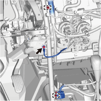
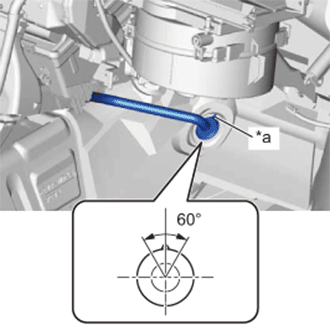
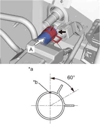
| 13. CONNECT DRAIN COOLER HOSE |
Install the drain cooler hose as shown in the illustration.
Text in Illustration *a UP Mark - NOTICE:
- Install the drain hose with its UP mark facing upward, within the 60 degree range shown in the illustration.
- Install the drain hose without twisting it.
 |
| 14. INSTALL REAR NO. 3 AIR DUCT (for Cold Area Specification Vehicles) |
Install the 2 claws and install the air duct.
| 15. INSTALL REAR NO. 4 AIR DUCT (for Cold Area Specification Vehicles) |
Install the 2 claws and install the air duct.
| 16. INSTALL REAR NO. 2 AIR DUCT (for Cold Area Specification Vehicles) |
Install the 2 claws and install the air duct.
Return the floor carpet.
 |
| 17. INSTALL DEFROSTER NOZZLE ASSEMBLY |
Engage the 2 claws and 3 guides, then install the defroster nozzle.
Engage the clamps and connect the connectors, then connect the wire harness.
| 18. INSTALL HEATER TO REGISTER DUCT ASSEMBLY |
Engage the 3 claws and install the heater to register duct.
| 19. INSTALL STEERING COLUMN ASSEMBLY |
| 20. INSTALL LOWER INSTRUMENT PANEL SUB-ASSEMBLY |
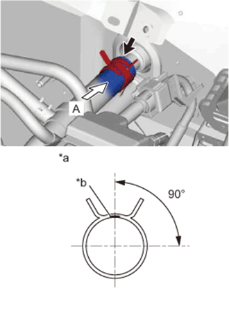
| 21. CONNECT HEATER WATER INLET HOSE A |
Connect the heater water inlet hose onto the air conditioning unit.
Text in Illustration *a View A *b White Paint Mark - HINT:
- Perform the installation with the hose clip and mark at the correct angle.
 |
| 22. CONNECT HEATER WATER OUTLET HOSE A |
Connect the heater water outlet hose onto the air conditioning unit.
Text in Illustration *a View A *b Purple Paint Mark - HINT:
- Perform the installation with the hose clip and mark at the correct angle.
 |
| 23. CONNECT AIR CONDITIONER TUBE AND ACCESSORY ASSEMBLY |
Remove the vinyl tape from air conditioner tube, liquid tube and the connecting portion of the unit.
Apply sufficient compressor oil (ND-OIL8) to 2 new O-rings and the connecting part of the air conditioner tube and liquid tube.
- Compressor oil:
- ND-OIL8 or equivalent
Install the 2 O-rings onto the air conditioner tube and liquid tube.
Securely connect the air conditioner tube and liquid tube to the air conditioning unit.
Turn the hook connector in the direction indicated by the arrow in the illustration.
 |
Insert the pipe joints securely into the fitting holes and tighten the bolt.
- Torque:
- 9.8 N*m{100 kgf*cm, 87 in.*lbf}
| 24. INSTALL COWL TOP OUTER PANEL |
Install the outer cowl top panel with the 8 bolts.
- Torque:
- 7.0 N*m{71 kgf*cm, 62 in.*lbf}
Engage the 2 clamps and install the wire harness.
| 25. INSTALL COWL TOP TO COWL INNER BRACE |
Install the cowl top to cowl brace with the 2 bolts.
- Torque:
- 7.0 N*m{71 kgf*cm, 62 in.*lbf}
| 26. INSTALL FRONT AIR SHUTTER SEAL RH |
- HINT:
- Use the same procedure for the RH and LH sides.
| 27. INSTALL FRONT NO. 1 VENTILATOR SEAL |
Engage the clip and install the front No. 1 ventilator seal.
| 28. INSTALL WINDSHIELD WIPER MOTOR AND LINK |
| 29. CONNECT CABLE TO NEGATIVE BATTERY TERMINAL |
- Torque:
- 5.4 N*m{55 kgf*cm, 48 in.*lbf}
| 30. ADD ENGINE COOLANT (for 1NZ-FE) |
| 31. CHARGE REFRIGERANT |
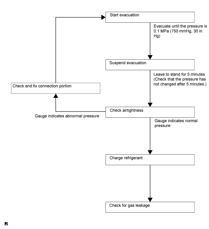
- HINT:
- Charge refrigerant in accordance with the equipment manual.
Perform vacuum purging using a vacuum pump.
Charge refrigerant HFC-134a (R134a).
- SST
- 09985-20010(09985-02010,09985-02050,09985-02060,09985-02070,09985-02080,09985-02090,09985-02110,09985-02130,09985-02140,09985-02150)
- Standard:
- 330 to 390 g (11.6 to 13.8 oz.)
- NOTICE:
- Do not start the engine before charging it with refrigerant as the cooler compressor does not work properly without sufficient refrigerant. This could cause the compressor to overheat.
- HINT:
- The relationship between the refrigerant charge amount and the pressure is as follows.
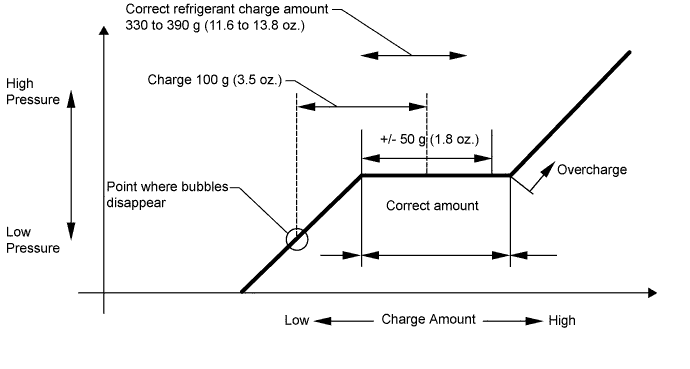
- High Charge Range:
If the refrigerant is overcharged, the pressure rises on the high-pressure side. High-pressure cut off frequently occurs. This causes insufficient cooling performance and also insufficient compressor lubrication. - Low Charge Range:
A shortage of refrigerant causes insufficient cooling performance and low circulation of refrigerant oil, which shortens the compressor life. Operation with insufficient coolant raises the refrigerant temperature and causes heat deterioration of the rubber seals and hoses. Cracking and subsequent refrigerant leakage may occur.
Install the caps onto the service valves on the refrigerant line.
| 32. INSPECT FOR COOLANT LEAK (for 1NZ-FE) |
| 33. WARM UP ENGINE |
- NOTICE:
- Warm up the engine at less than 2000 rpm for 1 minute or more after charging it with refrigerant.
| 34. INSPECT FOR REFRIGERANT LEAK |
After recharging the refrigerant gas, check for refrigerant gas leakage using a halogen leak detector.
Perform the operation as follows:
- Stop the engine.
- Secure good ventilation (the halogen leak detector may react to volatile gases other than refrigerant, such as evaporated gasoline or exhaust gas).
- Repeat the test 2 or 3 times.
- Make sure that some refrigerant remains in the refrigeration system.
When the compressor is off: approximately 392 to 588 kPa (4 to 6 kgf/cm2, 57 to 85 psi)
- HINT:
- It is impossible for the above pressure to be maintained if there is leakage.
- Stop the engine.
Using the halogen leak detector, check the refrigerant line, especially at the connection points, for leakage.
Text in Illustration *1 Halogen Leak Detector
 |
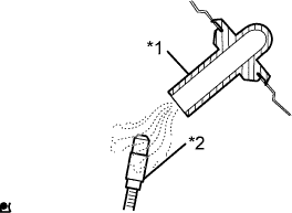
Bring the halogen leak detector close to the drain hose before performing the test.
Text in Illustration *1 Drain Hose *2 Halogen Leak Detector - HINT:
- After the blower motor has stopped, leave the cooling unit for at least 15 minutes.
- Place the halogen leak detector sensor under the drain hose.
- When bringing the halogen leak detector close to the drain hose, make sure that the halogen leak detector does not react to other volatile gases.
 |
If no gas leakage is detected from the drain hose, remove the blower motor from the cooling unit. Insert the halogen leak detector sensor into the unit and perform the test.
Disconnect the pressure switch connector and leave it for approximately 20 minutes. Bring the halogen leak detector close to the pressure switch and perform the test.