INSTALL REAR NO. 3 AIR DUCT (for Cold Area Specification Vehicles)
INSTALL REAR NO. 1 AIR DUCT (for Cold Area Specification Vehicles)
INSTALL REAR NO. 2 AIR DUCT (for Cold Area Specification Vehicles)
INSTALL BRAKE PEDAL SUPPORT SUB-ASSEMBLY (for Manual Transaxle)
INSTALL BRAKE MASTER CYLINDER PUSH ROD CLEVIS (for Manual Transaxle)
INSTALL SHIFT LEVER KNOB SUB-ASSEMBLY (for Manual Transaxle)
Air Conditioning Unit (For Sedan) -- Installation |
| 1. INSTALL AIR CONDITIONING UNIT |
 |
Install the air conditioning unit with the 3 screws.
| 2. INSTALL AIR CONDITIONING AMPLIFIER ASSEMBLY |
 |
Install the air conditioning amplifier with the screw.
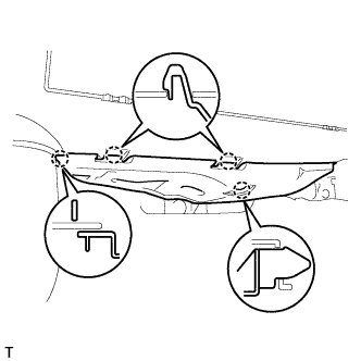
| 3. INSTALL INSTRUMENT PANEL REINFORCEMENT |
 |
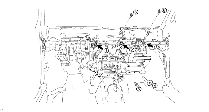
Provisionally tighten the air conditioning unit with the 3 screws.
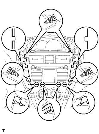
Install the instrument panel reinforcement and the air conditioning unit with the 9 bolts.

Install the 3 screws, 3 bolts and the nut in the sequence shown in the illustration.
- Torque:
- 4.0 N*m{41 kgf*cm, 35 in.*lbf}for screw
- 9.8 N*m{100 kgf*cm, 87 in.*lbf}for nut
- 9.8 N*m{100 kgf*cm, 87 in.*lbf}for bolt
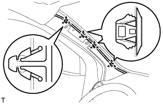
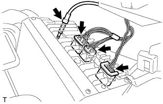
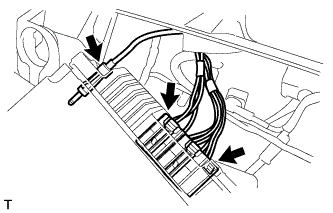
Install the wire harness with the clamps and connect the connectors.
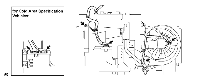
Engage the clamps.

Install the ground wire with the bolt.
- Torque:
- 3.2 N*m{33 kgf*cm, 28 in.*lbf}
 |
Install the ground wire with the bolt. (for Cold area specification vehicles)
- Torque:
- 8.0 N*m{82 kgf*cm, 71 in.*lbf}
 |
Install the drain hose into the position shown in the illustration.
- NOTICE:
- Install the drain hose with its UP mark facing upward, within the 60 degree range shown in the illustration.
- Install the drain hose without twisting it.
 |
| 4. INSTALL CONNECTOR NO. 2 HOLDER |
 |
Connect the connectors and install the wire harness.
Install the connector holder with the bolt.
- Torque:
- 3.2 N*m{33 kgf*cm, 28 in.*lbf}
 |
| 5. INSTALL MAIN BODY ECU (DRIVER SIDE J/B) |
 |
Install the main body ECU with the 2 bolts.
- Torque:
- 3.2 N*m{33 kgf*cm, 28 in.*lbf}
Connect the 5 connectors and the 3 clamps.
 |
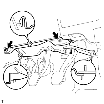
| 6. INSTALL INSTRUMENT PANEL BRACE SUB-ASSEMBLY |
 |
Install the instrument panel brace with the bolt, screw and nut.
- Torque:
- 9.8 N*m{100 kgf*cm, 87 in.*lbf}for screw
- 9.8 N*m{100 kgf*cm, 87 in.*lbf}for nut
- 9.8 N*m{100 kgf*cm, 87 in.*lbf}for bolt
Engage the clamp.
| 7. INSTALL REAR NO. 3 AIR DUCT (for Cold Area Specification Vehicles) |
 |
Engage the 4 claws and install the air duct.
| 8. INSTALL REAR NO. 1 AIR DUCT (for Cold Area Specification Vehicles) |
 |
Engage the 2 claws and install the air duct.
| 9. INSTALL REAR NO. 2 AIR DUCT (for Cold Area Specification Vehicles) |
 |
Engage the 4 claws and install the air duct.
| 10. INSTALL DEFROSTER NOZZLE ASSEMBLY |
 |
Engage the 5 claws and install the defroster nozzle.
Connect the 3 clamps and connector and install the wire harness.
| 11. INSTALL HEATER TO REGISTER DUCT ASSEMBLY |
 |
Engage the 3 claws and install the heater to register duct.
| 12. INSTALL STEERING COLUMN ASSEMBLY |
Install the steering column assembly onto the instrument panel reinforcement assembly with the bolt and 2 nuts.
- Torque:
- 25 N*m{255 kgf*cm, 18 ft.*lbf}
 |
Connect all the connectors and clamp the wire harnesses onto the steering column assembly bracket.
| 13. INSTALL BRAKE PEDAL SUPPORT SUB-ASSEMBLY (for Manual Transaxle) |
 |
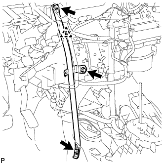
Install the pedal support with the bolt and 4 nuts.
- Torque:
- Bolt:
- 24 N*m{241 kgf*cm, 17 ft.*lbf}
- Nut:
- 9.0 N*m{92 kgf*cm, 80 in.*lbf}
| 14. INSTALL BRAKE MASTER CYLINDER PUSH ROD CLEVIS (for Manual Transaxle) |
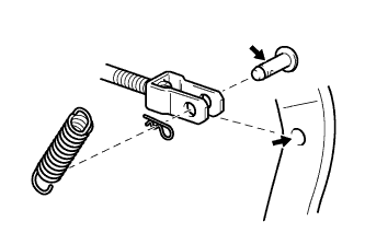
Apply lithium soap base glycol grease to the push rod pin.
Install the push rod clevis with the push rod pin and clip.
 |
Install the brake pedal return spring.
| 15. INSTALL BRAKE PEDAL (for Automatic Transaxle) |
Apply MP grease No. 2 to the brake master cylinder push rod clevis pin and installation surfaces.
Install the 2 brake pedal bushes, and install the brake pedal with the nut and brake pedal shaft.
- Torque:
- 37 N*m{375 kgf*cm, 27 ft.*lbf}
Apply lithium soap base glycol grease to the brake master cylinder push rod clevis pin and installation surfaces.
 |
Connect the brake master cylinder push rod clevis to the brake pedal with the brake master cylinder push rod clevis pin, install the clip onto the brake master cylinder push rod clevis pin, and then install the brake pedal return spring.
| 16. INSTALL STEERING SLIDING YOKE SUB-ASSEMBLY |
 |
Align the matchmarks and install the sliding yoke onto the power steering assembly with bolt B.
- Torque:
- 35 N*m{360 kgf*cm, 26 ft.*lbf}
Tighten bolt A.
- Torque:
- 35 N*m{360 kgf*cm, 26 ft.*lbf}
| 17. INSTALL COLUMN HOLE COVER SILENCER SHEET |
Install the column hole cover plate with the 2 clips.
 |
Install the floor carpet.
| 18. INSTALL INSTRUMENT PANEL SUB REINFORCEMENT |
Align the 2 claws and install the reinforcement instrument panel sub with the 2 bolts.
 |
| 19. CONNECT POWER STEERING ECU |
Connect the 2 steering column assembly connectors to the power steering ECU.
 |
Install the power steering motor harness and torque sensor wire harness clamps onto the side of the power steering ECU.
Tilt the steering column assembly up and down to make sure that the power steering motor harness and torque sensor wire harness do not interfere with any components.
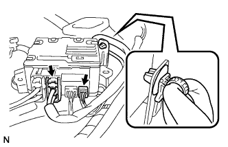
| 20. INSTALL COMBINATION SWITCH ASSEMBLY |
Install the combination switch assembly onto the steering column assembly with the clamp.
 |
Connect all the connectors to the turn signal switch with spiral cable.
| 21. INSTALL STEERING COLUMN COVER |
Engage the claw to install the steering column upper cover.
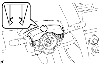 |
Engage the 2 claws to install the steering column lower cover.
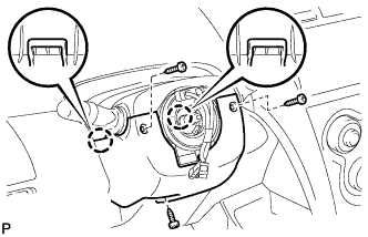 |
Install the 3 screws.
| 22. INSTALL STEERING WHEEL ASSEMBLY |
Align the matchmarks and install the steering wheel assembly onto the steering column assembly.
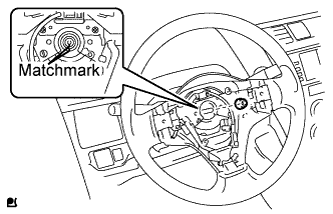 |
Install the nut.
- Torque:
- 50 N*m{510 kgf*cm, 37 ft.*lbf}
Connect all connectors to the spiral cable.
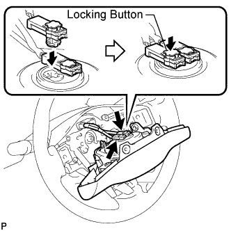
| 23. INSTALL STEERING PAD |
 |
- NOTICE:
- Do not use a steering pad that has been dropped.
Confirm that the ignition switch is turned to OFF.
Confirm that the negative battery terminal is detached.
- CAUTION:
- Do not begin the operation for at least 90 seconds after the negative battery terminal is detached.
Connect the horn terminal.
Connect the airbag connector.
- NOTICE:
- Match the color of the airbag connector with that of the steering pad assembly, and install the airbag connector.
- Securely lock the locking button.
Install the steering pad.
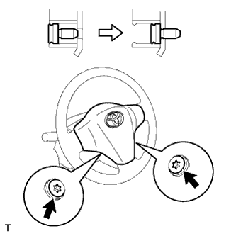 |
Using "Torx" socked wrench T30, tighten the 2 bolts.
- Torque:
- 8.8 N*m{90 kgf*cm, 78 in.*lbf}
- NOTICE:
- Tighten the 2 bolts while holding the steering pad to prevent it moving upward.
| 24. INSTALL LOWER INSTRUMENT PANEL SUB-ASSEMBLY |
Using a nipper, cut off both ends of the runner portion shown in the illustration (When installing a new one).
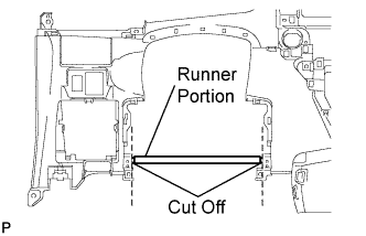 |
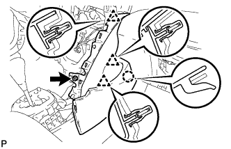
Install the lower instrument panel with the 6 <D> bolts, 2 <E> bolts, screw <G> and screw <H>.
- NOTICE:
- Do not excessively tighten the <D> bolts, as this may damage the area not being tightened.
Connect the clamps and connectors.

Engage the 2 claws and connect the DLC3 connector.
 |
| 25. CONNECT HOOD LOCK CONTROL LEVER SUB-ASSEMBLY |
 |
Engage the 3 claws to connect the control lever.
| 26. CONNECT ANTENNA CORD SUB-ASSEMBLY |
Connect the 5 antenna cord clamps.
 |
| 27. INSTALL INSTRUMENT PANEL BOX |
 |
Insert the stopper of the instrument panel box from the cutout of the instrument panel lower.
Engage the 2 hinges with the instrument panel open.
 |
Close the instrument panel box.
| 28. INSTALL INSTRUMENT PANEL LOWER FINISH PANEL SUB-ASSEMBLY |
 |
Install the 2 <A> screws.
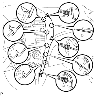
Engage the 7 claws and install the instrument panel lower finish panel.
 |
| 29. INSTALL INSTRUMENT PAD LOWER RH |
Engage the claw and 3 clips and install the instrument pad lower.
 |
Install screw <I>.
| 30. INSTALL INSTRUMENT PAD LOWER LH |
Engage the claw and 3 clips and install the instrument pad lower.
 |
Install screw <I>.
| 31. INSTALL REAR CONSOLE BOX ASSEMBLY |
Engage the 4 claws and install the rear console box.
 |
Install the 2 bolts and 2 screws.
Connect the clamp.
| 32. INSTALL CONSOLE BOX CARPET |
Install the console box carpet.
 |
| 33. INSTALL CONSOLE UPPER REAR PANEL SUB-ASSEMBLY |
Connect the connector.
 |
Engage the 3 clips and 3 claws and install the console upper rear panel.
| 34. INSTALL UPPER CONSOLE PANEL SUB-ASSEMBLY |
Engage the 5 clips and the claw and install the upper console panel.
 |
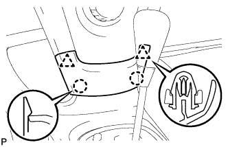
| 35. INSTALL SHIFT LEVER KNOB SUB-ASSEMBLY (for Manual Transaxle) |
Install the shift lever knob.
 |
| 36. INSTALL COWL SIDE TRIM BOARD RH |
Engage the stud bolt and the claw and install the cowl side trim board.
 |
| 37. INSTALL COWL SIDE TRIM BOARD LH |
- HINT:
- Use the same procedure as for the RH side.
| 38. INSTALL INSTRUMENT PANEL UNDER COVER SUB-ASSEMBLY RH |
Engage the 4 claws and install the instrument panel under cover.
 |
| 39. INSTALL INSTRUMENT PANEL UNDER COVER SUB-ASSEMBLY LH |
Engage the 3 claws and install the instrument panel under cover.
 |
Tighten the 2 screws.
| 40. INSTALL FRONT DOOR SCUFF PLATE RH |
Engage the 11 claws and install the front door scuff plate.
 |
| 41. INSTALL FRONT DOOR SCUFF PLATE LH |
- HINT:
- Use the same procedure as for the RH side.
| 42. INSTALL UPPER INSTRUMENT PANEL SUB-ASSEMBLY |
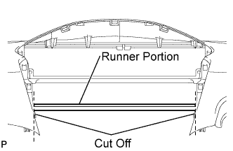 |
Using a nipper, cut off both ends of the runner portion shown in the illustration (When installing a new one).
Engage the 5 claws at the front side of the instrument panel.
Engage the 7 clips at the rear side of the instrument panel.
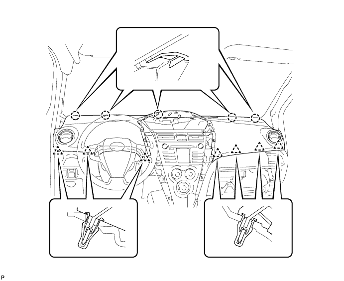
Install the upper instrument panel with the 2 <C> bolts and the 2 <B> screws.
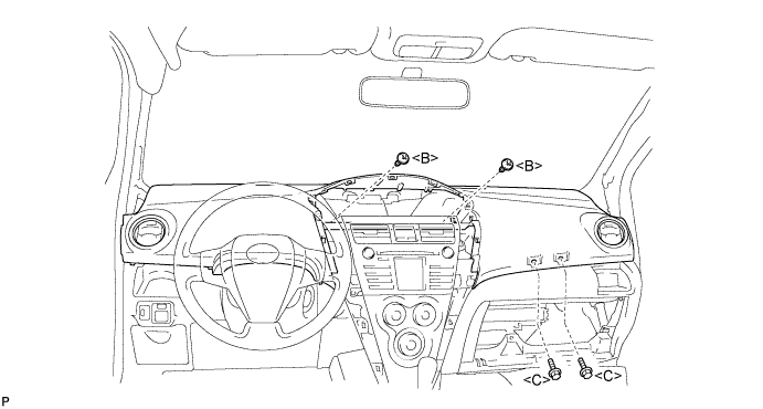
- Torque:
- 20 N*m{204 kgf*cm, 15 ft.*lbf} for bolt <C>
Connect the passenger airbag connector and clamp.
 |
| 43. INSTALL GLOVE COMPARTMENT DOOR ASSEMBLY |
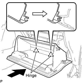 |
Engage the claws of the hinge portions by pushing the glove compartment door in the horizontal direction to install the glove compartment door assembly.
- NOTICE:
- Engage the claw by pushing it in the horizontal direction, otherwise, installation failure caused by excessive play around the hinge portion will result.
Slightly flex the upper portion of the glove compartment door assembly to engage the stopper.
 |
Install the 2 glove compartment door stoppers onto the glove compartment door.
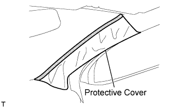
| 44. INSTALL FRONT PILLAR GARNISH RH |
w/ Curtain Shield Airbag:
Remove the piece of cloth or nylon.
 |
Install the 3 clamps.
 |
Connect the antenna connector.
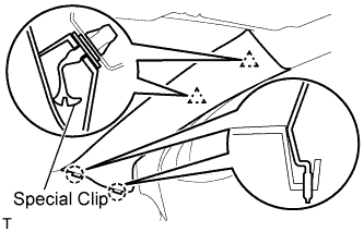
w/ Curtain Shield Airbag:
Install 2 new special clips and the clip onto the front pillar garnish.
Engage the 2 clips and the 2 claws and install the front pillar garnish.
 |
w/o Curtain Shield Airbag:
Engage the 2 clips and the 2 claws and install the front pillar garnish.
 |
| 45. INSTALL FRONT PILLAR GARNISH LH |
w/ Curtain Shield Airbag:
Remove the piece of cloth or nylon.
 |
Install the 4 clamps.
 |
w/ Curtain Shield Airbag:
Install 2 new special clips and the clip onto the front pillar garnish.
Engage the 2 clips and the 2 claws and install the front pillar garnish.
 |
w/o Curtain Shield Airbag:
Engage the 2 clips and the 2 claws and install the front pillar garnish.
 |
| 46. INSTALL FRONT DOOR OPENING TRIM WEATHERSTRIP RH |
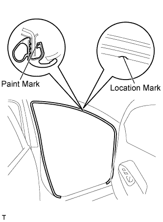
Align the location mark with the paint mark first, and install the front door opening trim weatherstrip, as shown in the illustration.
- Paint mark:
Area Color RH side Blue LH side Pink
 |
| 47. INSTALL FRONT DOOR OPENING TRIM WEATHERSTRIP LH |
- HINT:
- Use the same procedure as for the RH side.
| 48. CONNECT AIR INLET DAMPER CONTROL CABLE SUB-ASSEMBLY |
 |
Engage the 2 claws and connect the air inlet damper control cable.
| 49. CONNECT DEFROSTER DAMPER CONTROL CABLE SUB-ASSEMBLY |
 |
Engage the 2 claws and connect the defroster damper control cable.
| 50. CONNECT AIR MIX DAMPER CONTROL CABLE SUB-ASSEMBLY |
 |
Engage the 2 claws and connect the air mix control cable clamp.
Connect the air mix damper control cable to the clamp.
| 51. INSTALL AIR CONDITIONING PANEL ASSEMBLY |
 |
Connect the 3 connectors and the 4 clamps.
Engage the 4 clips and 2 claws and install the air conditioning panel.
 |
| 52. INSTALL STEREO OPENING COVER (w/o Radio Receiver) |
 |
Install the stereo opening cover with the 4 screws.
| 53. INSTALL RADIO RECEIVER ASSEMBLY |
for Integrated with Panel:
Connect the plug.
Connect the 3 radio connectors.
Align the 2 bosses of the instrument panel with the hole in the radio bracket.
Engage the 4 clips and 4 claws and install the radio receiver.
Tighten the 4 bolts.
Connect the hazard warning signal switch connector.

 |
except Integrated with Panel:
Connect the plug.
Connect the 2 radio connectors.
Align the 2 bosses of the instrument panel with the hole in the radio bracket.
Install the radio receiver with the 4 bolts.

 |
| 54. INSTALL INSTRUMENT CLUSTER FINISH PANEL CENTER SUB-ASSEMBLY |
 |
Engage the 2 claws and 4 clips and install the instrument cluster finish panel center.
| 55. INSTALL COMBINATION METER ASSEMBLY |
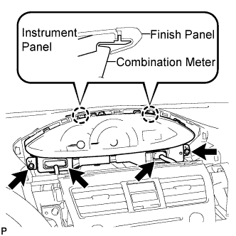 |
Install the combination meter assembly with the 2 screws.
- NOTICE:
- Install the meter by inserting the ribbed portions of the meter between the instrument panel and meter cluster.
Connect the 2 connectors.
| 56. INSTALL INSTRUMENT CLUSTER FINISH PANEL NO.1 |
 |
Fit the 2 claws of the instrument cluster finish panel into the upper instrument cluster finish panel center.
Engage the 5 claws and 5 clips and install the instrument cluster finish panel.
 |
| 57. INSTALL INSTRUMENT PANEL FINISH PANEL END RH |
 |
Engage the 6 claws and 3 clips and install the instrument panel finish panel end RH.
| 58. INSTALL INSTRUMENT PANEL FINISH PANEL END LH |
 |
Engage the 6 claws and 3 clips and install the instrument panel finish panel end LH.
| 59. INSTALL INSTRUMENT PANEL FINISH PANEL LOWER CENTER |
 |
Engage the 2 claws and 2 clips and install the instrument panel finish panel lower center.
| 60. CONNECT HEATER WATER INLET HOSE |
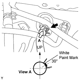 |
Install the heater water inlet hose onto the heater unit.
- NOTICE:
- Perform the installation with the hose clip and mark at the correct angle as shown in the illustration.
| 61. CONNECT HEATER WATER OUTLET HOSE |
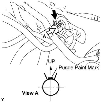 |
Install the heater water outlet hose onto the heater unit.
- NOTICE:
- Perform the installation with the hose clip and mark at the correct angle as shown in the illustration.
| 62. INSTALL LIQUID TUBE SUB-ASSEMBLY |
Remove the vinyl tape from the liquid tube and the connecting portion of the unit.
Apply sufficient compressor oil (ND-OIL8) to a new O-ring and the connecting part of the liquid tube.
- Compressor oil:
- ND-OIL8 or the equivalent
Install the O-ring onto the liquid tube.
Connect the liquid tube to the unit.
| 63. INSTALL SUCTION TUBE SUB-ASSEMBLY |
Remove the vinyl tape from the suction tube and the connecting part of the unit.
Apply sufficient compressor oil (ND-OIL8) to a new O-ring and the connecting part of the suction tube.
- Compressor oil:
- ND-OIL8 or the equivalent
Install the O-ring onto the suction tube.
Insert the tube joints securely into the fitting holes and tighten the bolt.
- Torque:
- 9.8 N*m{100 kgf*cm, 87 in.*lbf}
 |
| 64. ADD ENGINE COOLANT (for 1NZ-FE) |
Tighten all the plugs.
Pour engine coolant into the radiator assembly until it overflows.
- Capacity:
- M/T 4.8 liters (5.1 USqts, 4.5 lmp. qts)
- A/T 4.7 liters (5.0 USqts, 4.4 lmp. qts)
- NOTICE:
- Do not substitute water for engine coolant.
- HINT:
- Use of improper engine coolant may damage the engine coolant system.
- Use only Toyota Super Long Life Coolant or similar high quality ethylene glycol based non-silicate, non-amine, non-nitrite, and non-borate engine coolant with long-life hybrid organic acid technology (coolant with long-life hybrid organic acid technology consists of a combination of low phosphates and organic acids).
Check the engine coolant level inside the radiator assembly by squeezing the inlet and outlet radiator hoses several times by hand. If the engine coolant level goes down, add engine coolant.
Install the radiator cap sub-assembly securely.
Slowly pour engine coolant into the radiator reservoir until it reaches the FULL line.
Bleed air from the cooling system.
Warm up the engine until the thermostat opens. While the thermostat is open, circulate the coolant for several minutes.
- HINT:
- The thermostat open timing can be confirmed by pressing the No. 2 radiator hose by hand, and checking when when the coolant starts to flow inside the hose.
Maintain the engine speed at 2,000 to 2,500 rpm and warm up the engine until the cooling fan operates.
Press the No. 2 radiator hose and No. 3 radiator hose several times by hand to bleed air.
- NOTICE:
- When pressing the radiator houses
- Wear protective glove.
- Be careful as the radiator hoses are hot.
- Keep your hands away form the radiator fan.
Stop the engine and wait until the coolant cools down.
If the engine coolant level is below the full level, perform steps (b) through (g) again and repeat the operation until the engine coolant level stays at the full level.
Recheck the engine coolant level inside the radiator reservoir tank assembly. If it is below the full level, add engine coolant.
| 65. CONNECT CABLE TO NEGATIVE BATTERY TERMINAL |
- Torque:
- 5.4 N*m{55 kgf*cm, 48 in.*lbf}
| 66. CHECK SRS WARNING LIGHT |
| 67. CHARGE REFRIGERANT |
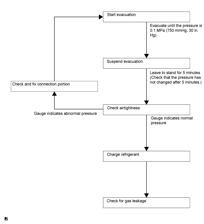
- NOTICE:
- Charge refrigerant in accordance with equipment manual.
Perform vacuum purging using a vacuum pump.
Charge refrigerant HFC-134a (R134a).
- SST
- 09985-20010(09985-02010,09985-02050,09985-02060,09985-02070,09985-02080,09985-02090,09985-02110,09985-02130,09985-02140,09985-02150)
- Standard:
- 330 to 390g (11.64 to 13.76oz.)
- NOTICE:
- Do not start the engine before charging it with refrigerant as the cooler compressor doesn't work properly without sufficient refrigerant. This could cause the compressor to overheat.
- HINT:
- The relationship between refrigerant charge amount and pressure is as follows.

- High Charge Range:
If refrigerant is overcharged, pressure rises on the high-pressure side. High-pressure cut off frequently occurs. This causes insufficient cooling performance and also insufficient compressor lubrication. - Low Charge Range:
Shortage of refrigerant causes insufficient cooling performance and low circulation of refrigerant oil, which shortens compressor life. Operation with insufficient coolant raises refrigerant temperature and causes heat deterioration of rubber seals and hoses. Cracking and thus refrigerant leakage may occur.
Install the caps onto the service valves on the refrigerant line.
| 68. WARM UP ENGINE |
- NOTICE:
- Warm up the engine at less than 2,000 rpm for 1 minute or more after charging it with refrigerant.
| 69. CHECK FOR ENGINE COOLANT LEAK (for 1NZ-FE) |
- CAUTION:
- To avoid the danger of being burned, do not remove the water filler cap sub-assembly while the engine and radiator assembly are still hot. Thermal expansion will cause hot engine coolant and steam to blow out from the radiator assembly.
Fill the radiator assembly with engine coolant, and attach a radiator cap tester.
 |
Pump the tester to 118 kPa (1.2 kgf/cm2, 17.1 psi), and then check that the pressure does not drop.
If the pressure drops, check the hoses, radiator assembly and water pump assembly for leaks. If there are no signs or traces of external engine coolant leaks, check the heater core, cylinder block and head.
| 70. CHECK FOR REFRIGERANT LEAK |
After recharging the refrigerant gas, check for refrigerant gas leakage using a halogen leak detector.
Perform the operation as follows:
- Stop the engine.
- Secure good ventilation (the halogen leak detector may react to volatile gases other than refrigerant, such as evaporated gasoline or exhaust gas).
- Repeat the test 2 or 3 times.
- Make sure that some refrigerant remains in the refrigeration system.
When compressor is off: approximately 392 to 588 kPa (4 to 6 kgf*cm2, 57 to 85 psi)
- HINT:
- It is impossible for the above pressure to be maintained if there is leakage.
- Stop the engine.
Using the halogen leak detector, check the refrigerant line, especially the connection points, for leakage.
 |
Bring the halogen leak detector close to the drain hose before performing the test.
- HINT:
- After the blower motor has stopped, leave the cooling unit for at least 15 minutes.
- Place the halogen leak detector sensor under the drain hose.
- When bringing the halogen leak detector close to the drain hose, make sure that the halogen leak detector does not react to the volatile gases.
 |
If a gas leak is not detected from the drain hose, remove the blower motor from the cooling unit. Insert the halogen leak detector sensor into the unit and perform the test.
Disconnect the pressure switch connector and leave it for approximately 20 minutes. Bring the halogen leak detector close to the pressure switch and perform the test.
| 71. POSITION FRONT WHEELS FACING STRAIGHT AHEAD |
| 72. PERFORM CALIBRATION OF TORQUE SENSOR ZERO POINT |