Vehicle Interior. Yaris. Ncp93, 131
Heating Air Conditioning. Yaris. Ncp93, 131
Air Conditioning System (For Sedan) -- Terminals Of Ecu |
| CHECK AIR CONDITIONING AMPLIFIER |
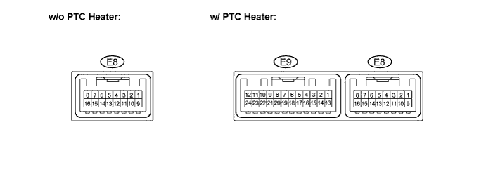
- HINT:
- Check from the rear of the connector while it is connected to the air conditioning amplifier.
| Symbols (Terminals No.) | Wiring Color | Terminal Description | Condition | Specified Condition |
| S5-3 (E8-1) - GND (E8-12) | Y - W-B | Power supply for pressure sensor | Ignition switch: ON | 4.5 to 5.5 V |
| TX+ (E8-2) - GND (E8-12) | V - W-B | CAN communication line | Ignition switch: ON | Pulse generation (see waveform 1) |
| TX- (E8-3) - GND (E8-12) | W - W-B | CAN communication line | Ignition switch: ON | Pulse generation (see waveform 2) |
| SG-2 (E8-4) - Body ground | L - Body ground | Ground for evaporator temperature sensor | Always | Below 1.0 Ω |
| TAM (E8-5) - SG-1 (E8-11) | W - B | Ambient temperature sensor signal | Ignition switch: ON | 1.35 to 1.75 V |
| Ambient temperature: 25 °C | ||||
| PRE (E8-6) - SG-1 (E8-11) | GR - B | A/C pressure sensor signal | Refrigerant pressure: normal | 0.76 to 4.74 V |
| PRE (E8-6) - SG-1 (E8-11) | GR - B | A/C pressure sensor signal | Refrigerant pressure: abnormal (less than 0.196 MPa [2.0 kgf/cm2] or more than 3.14 MPa [32 kgf/cm2]) | Below 0.76 V or 4.74 V or more |
| SOL+ (E8-7) - GND (E8-12) | LG - W-B | A/C compressor operation signal | Engine idling | Pulse generation (see waveform 3) |
| Blower switch: 1 | ||||
| A/C switch: ON | ||||
| IG+ (E8-8) - GND (E8-12) | Y - W-B | Power source (IG) | Ignition switch: ON | 11 to 14 V |
| SBLW (E8-9) - GND (E8-12) | BR - W-B | Blower motor ON signal | Ignition switch: ON | 11 to 14 V → 0 V |
| Blower switch: 0 → 1 | ||||
| TE (E8-10) - SG-2 (E8-4) | GR - L | Evaporator temperature sensor signal | Ignition switch: ON | 1.0 to 1.3 V |
| Temperature near evaporator: 15°C (59°F) | ||||
| SG-1 (E8-11) - Body ground | B - Body ground | Ground for ambient temperature sensor | Always | Below 1.0 Ω |
| GND (E8-12) - Body ground | W-B - Body ground | Ground for main power supply | Always | Below 1.0 Ω |
| A/C (E8-15) - GND (E8-12) | LG - W-B | A/C switch signal | Ignition switch: ON | Below 1 V → 11 to 14 V |
| Defroster: OFF | ||||
| A/C switch: OFF → ON | ||||
| Defroster mode detection switch signal | Ignition switch: ON | Below 1 V → 11 to 14 V | ||
| A/C switch: OFF | ||||
| Defroster: OFF → ON | ||||
| LED (E8-16) - Body ground | P - Body ground | A/C switch indicator signal | Engine idling | 11 to 14 V → Below 4 V |
| A/C switch: ON | ||||
| Blower switch: 0 → 1 | ||||
| PTC1* (E9-9) - GND (E8-12) | V - W-B | PTC heater relay operation signal | Engine idling | Below 1 V → 11 to 14 V |
| No. 3 heater control knob: Max Hot | ||||
| Engine coolant temperature: Below 65°C (149°F) | ||||
| Ambient temperature: Below 10°C (50°F) | ||||
| Blower switch: 0 → 1 | ||||
| Waiting time: 10 seconds | ||||
| PTC2* (E9-10) - GND (E8-12) | BR - W-B | PTC heater relay operation signal | Engine idling | Below 1 V → 11 to 14 V |
| No. 3 heater control knob: Max Hot | ||||
| Engine coolant temperature: Below 65°C (149°F) | ||||
| Ambient temperature: Below 10°C (50°F) | ||||
| Blower switch: 0 → 1 | ||||
| Waiting time: 20 seconds | ||||
| PTC3* (E9-12) - GND (E8-12) | R - W-B | PTC heater relay operation signal | Engine idling | Below 1 V → 11 to 14 V |
| No. 3 heater control knob: Max Hot | ||||
| Engine coolant temperature: Below 65°C (149°F) | ||||
| Ambient temperature: Below 10°C (50°F) | ||||
| Blower switch: 0 → 1 | ||||
| Waiting time: 30 seconds | ||||
| HEAT* (E9-14) - Body ground | LG - Body ground | MAX HOT switch detection signal | Ignition switch: ON | 11 to 14 V |
| No. 3 heater control knob: Max Hot | ||||
| HLS* (E9-23) - Body ground | LG - Body ground | Headlight control signal | Engine idling | 11 to 14 V → Below 1 V |
| Light control switch: OFF → HEAD | ||||
| ALT* (E9-24) - GND (E8-12) | P - W-B | Alternator operation signal | Engine idling | Pulse generation |
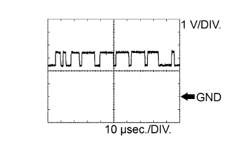
Waveform 1 (Reference) : Using an oscilloscope
CAN communication signal Terminal Name Between TX+ (E8-2) - GND (E8-12) Tester Range 1 V / DIV., 10 μsec. / DIV. Condition Ignition switch ON - HINT:
- The waveform varies depending on the CAN communication signal.
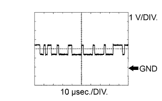
Waveform 2 (Reference) : Using an oscilloscope
CAN communication signal Terminal Name Between TX- (E8-3) - GND (E8-12) Tester Range 1 V / DIV., 10 μsec. / DIV. Condition Ignition switch ON - HINT:
- The waveform varies depending on the CAN communication signal.
Waveform 3 (Reference) : Using an oscilloscope
Compressor and pulley operation signal Terminal Name Between SOL+ (E8-7) - GND (E8-12) Tester Range 5 V / DIV., 500 μsec. / DIV. Condition Engine idling, Blower switch 1, A/C switch ON
 |
 |
 |