Meter / Gauge System (For Sedan) Speedometer Malfunction
DESCRIPTION
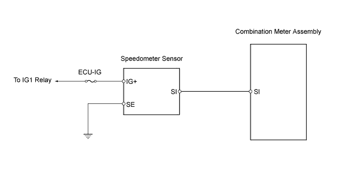
WIRING DIAGRAM
INSPECTION PROCEDURE
PERFORM ACTIVE TEST USING TECHSTREAM (SPEED METER)
READ VALUE USING TECHSTREAM (SPEED METER)
INSPECT SPEEDOMETER SENSOR
CHECK HARNESS AND CONNECTOR (SPEEDOMETER SENSOR - COMBINATION METER ASSEMBLY)
METER / GAUGE SYSTEM (for Sedan) - Speedometer Malfunction |
DESCRIPTION
The combination meter assembly controls the speedometer in accordance with vehicle speed signals from the speedometer sensor.
WIRING DIAGRAM
INSPECTION PROCEDURE
- HINT:
- If DTC U0129 has been stored, troubleshoot the CAN communication system first.
| 1.PERFORM ACTIVE TEST USING TECHSTREAM (SPEED METER) |
Connect the Techstream to the DLC3.
Turn the ignition switch ON and turn the tester ON.
Enter the following menus : Body Electrical / Combination Meter / Active Test.
- Body Electrical / Combination Meter / Active Test::
Tester Display
| Test Part
| Control Range
|
Speed Meter Operation
| 0/40/80/120 mph
0/40/80/120/160/200 km/h
| -
|
- OK:
- Vehicle speed displayed on the tester is approximately the same as that of the speedometer reading.
| 2.READ VALUE USING TECHSTREAM (SPEED METER) |
Connect the Techstream to the DLC3.
Turn the ignition switch ON and the tester ON.
Select the item below from the Data List, and read the value displayed on the Techstream.
- Body Electrical / Combination Meter / Data List::
Tester Display
| Measurement Item/Range
| Normal Condition
| Diagnostic Note
|
Vehicle Speed Meter
| Vehicle speed / Min.: 0 km/h (0mph), Max.: 255 km/h(158mph)
| Almost same as vehicle speed
(When vehicle is driving)
| -
|
- OK:
- Vehicle speed displayed on the tester is approximately the same as the actual vehicle speed.
| 3.INSPECT SPEEDOMETER SENSOR |
Remove the speedometer sensor.
Connect the positive (+) lead from the battery to terminal 1 and the negative(-) lead to terminal 2.
Connect the positive (+) lead from the tester to terminal 3 and the negative (-) lead to terminal 2.
Rotate the shaft.
Check that the voltage output between terminals 2 and 3 varies between 0V and 11V.
Reinstall the speedometer sensor.
| 4.CHECK HARNESS AND CONNECTOR (SPEEDOMETER SENSOR - COMBINATION METER ASSEMBLY) |
Disconnect the D1 combination meter assembly connector.
Disconnect the C21 speedometer sensor connector.
Measure the resistance
- Standard resistance:
Tester Connection
| Condition
| Specified Condition
|
D1-17 (SI) - C21-3 (SI)
| Always
| Below 1 Ω
|
C21-2 (SE) - Body ground
| Always
| Below 1 Ω
|
Reconnect the combination meter assembly connector.
Measure the voltage
- Standard voltage:
Tester Connection
| Switch Condition
| Specified Condition
|
C21-1 (IG+) - Body ground
| Ignition switch ON
| 11 to 14V
|
Reconnect the combination meter assembly and speedometer sensor connectors.
| | REPAIR OR REPLACE HARNESS OR CONNECTOR |
|
|