Vehicle Interior. Yaris. Ncp93, 131
Theft Deterrent Keyless Entry. Yaris. Ncp93, 131
Engine Immobiliser System (For Hatchback) -- Data List / Active Test |
| DATA LIST |
- HINT:
- Using the Techstream to read the Data List allows the values or states of switches, sensors, actuators and other items to be read without removing any parts. This non-intrusive inspection can be very useful because intermittent conditions or signals may be discovered before parts or wiring is disturbed. Reading the Data List information early in troubleshooting is one way to save diagnostic time.
- If the ignition switch cannot be turned to ON, communication with the Techstream can be performed by connecting the Techstream to the vehicle and turning a courtesy light switch on and off at intervals of 1.5 seconds or less until communication between the Techstream and vehicle begins.
- NOTICE:
- In the table below, the values listed under "Normal Condition" are reference values. Do not depend solely on these reference values when deciding whether a part is faulty or not.
Connect the Techstream to the DLC3.
Turn the ignition switch to ON.
Turn the Techstream on.
Enter the following menus: Body Electrical / Immobiliser / Data List.
Enter the following menus: Powertrain / Engine and ECT / Data List.
According to the display on the Techstream, read the Data List.
Immobiliser Tester Display Measurement Item/Range Normal Condition Diagnostic Note D Door Courtesy SW Not available / OFF or ON - - Key SW Unlock warning switch signal / OFF or ON OFF: No key in ignition key cylinder
ON: Key inserted in ignition key cylinder- IG SW*2 Ignition switch signal / OFF or ON OFF: Ignition switch ACC or off
ON: Ignition switch ON- Immobiliser*2 Engine immobiliser system status determined by transponder key ECU assembly / Set or Unset Set: Engine immobiliser set (engine start prohibited (no key in ignition key cylinder))
Unset: Engine immobiliser unset (engine start permitted (key inserted in ignition key cylinder))When the engine immobiliser system does not change to the unset state, this item can be used to determine if the cause is the transponder key ECU assembly. Response Key response to signal from transponder key ECU assembly / OK or NG OK: Key responds to signal from transponder key ECU assembly
NG: Key does not respond to signal from transponder key ECU assemblyProblems may be caused by the following: - A key from a different vehicle is being used.
- Malfunctions in the key, transponder key ECU assembly or transponder key amplifier.
Frame Error State of data sent from key / OK or NG OK: No problem with data sent from key
NG: Problem with data sent from keyProblems may be caused by the following: - Communication errors due to external electric wave noise.
- Malfunctions in the key, transponder key ECU assembly or transponder key amplifier.
Different Serial Number*1 Vehicle serial number / OK or NG OK: Signal from transponder chip and vehicle serial number stored in transponder key ECU assembly match
NG: Signal from transponder chip and vehicle serial number stored the transponder key ECU assembly do not matchProblems may be caused by the following: - A key from a different vehicle is being used.
- Malfunctions in the key, transponder key ECU assembly or transponder key amplifier.
Different Encrypt Code*1 Code status between transponder chip and transponder key ECU assembly / OK or NG OK: Codes of transponder chip and transponder key ECU assembly match
NG: Codes of transponder chip and transponder key ECU assembly do not matchProblems may be caused by the following: - A key from a different vehicle is being used.
- Malfunctions in the key, transponder key ECU assembly or transponder key amplifier.
Abnormal Status*1 Transponder chip status signal / OK or NG OK: Transponder chip status signal normal
NG: Transponder chip status signal malfunction (malfunction in code computation in key/transponder key ECU assembly)Problems may be caused by the following: - Communication errors due to external electric wave noise (LF).
- Malfunctions in the key, transponder key ECU assembly or transponder key amplifier.
Bcc Malfunction*1 Bcc signal status of transponder chip / OK or NG OK: Bcc signal normal
NG: Bcc signal malfunction (malfunction in code computation in key/transponder key ECU assembly)Problems may be caused by the following: - Communication errors due to external electric wave noise (LF).
- Malfunctions in the key, transponder key ECU assembly or transponder key amplifier.
Sub Key Whether sub-key ID code matches ID code registered in transponder key ECU assembly / Unreg or Reg Unreg: ID code of sub-key does not match ID code registered in transponder key ECU assembly
Reg: ID code of sub-key matches ID code registered in transponder key ECU assembly- Master Key Whether master key ID code matches ID code registered in transponder key ECU assembly / Unreg or Reg Unreg: ID code of master key does not match ID code registered in transponder key ECU assembly
Reg: ID code of master key matches ID code registered in transponder key ECU assembly- Transponder S-code Number of registered sub-keys / min.: 0, max.: 15 Number of registered sub-keys - Transponder M-code Number of registered master keys / min.: 0, max.: 15 Number of registered master keys - Reg Code Space Full Key registration code memory space full / No or Yes Yes: Cannot register any more key codes
No: Possible to register more key codes- +B +B judgment / Normal or Break Normal: Battery power supply normal
Break: Battery power supply malfunctioning- Antenna Coil Status Antenna coil condition / Normal or Fail Normal: Antenna coil normal
Fail: Antenna coil malfunctioning- EEPROM Status EEPROM status / OK or NG OK: Data OK
NG: Data error- E/G Start Permission*2 Engine start permission / NG or OK NG: Engine start not permitted
OK: Engine start permitted- Immobi ECU Comm Spd Immobiliser ECU communication speed / Unknown, 50bps, 200bps or No Res Unknown: ECU communication speed unknown
50bps: ECU communication speed 50 bps
200bps: ECU communication speed 200 bps
No Res: No response regarding ECU communication speed- The Number of DTCs Number of DTCs / Min.: 0, Max.: 255 Number of stored DTCs - - HINT:
- *1: This indicates that there is a problem with the communication format between the key and transponder key ECU assembly. Electric wave interference, key or transponder key ECU assembly malfunctions, the key of another vehicle being used, etc. are possible causes.
- *2: Refer to the following Data List items of an actual vehicle.
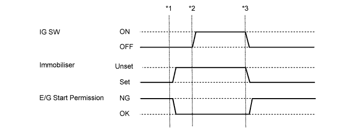
- *1: Without depressing the brake pedal (for Automatic Transaxle) or clutch pedal (for Manual Transaxle), insert the key into the ignition key cylinder and turn the ignition switch to ACC.
- *2: Without depressing the brake pedal (for Automatic Transaxle) or clutch pedal (for Manual Transaxle), turn the ignition switch to ON.
- *3: Turn the ignition switch off and remove the key from the ignition key cylinder.
Engine and ECT Tester Display Measurement Item/Range Normal Condition Diagnostic Note Immobiliser Fuel Cut Status of immobiliser fuel cut / ON or OFF - - - A key from a different vehicle is being used.
| ACTIVE TEST |
- HINT:
- Using the Techstream to perform Active Tests allows relays, VSVs, actuators and other items to be operated without removing any parts. This non-intrusive functional inspection can be very useful because intermittent operation may be discovered before parts or wiring is disturbed. Performing Active Tests early in troubleshooting is one way to save diagnostic time. Data List information can be displayed while performing Active Tests.
Connect the Techstream to the DLC3.
Turn the ignition switch to ON.
Turn the Techstream on.
Enter the following menus: Body Electrical / Immobiliser / Active Test.
According to the display on the Techstream, perform the Active Test.
Immobiliser Tester Display Test Part Control Range Diagnostic Note Security Indicator Theft Warning Indicator Light Assembly OFF / ON -