Steering Column Assembly (For Sedan) Disassembly
REMOVE STEERING SLIDING YOKE SUB-ASSEMBLY
REMOVE TRANSPONDER KEY AMPLIFIER
REMOVE STEERING COLUMN UPPER WITH SWITCH BRACKET ASSEMBLY
REMOVE IGNITION SWITCH LOCK CYLINDER ASSEMBLY
REMOVE UN-LOCK WARNING SWITCH ASSEMBLY
REMOVE KEY INTER LOCK SOLENOID
REMOVE IGNITION OR STARTER SWITCH ASSEMBLY
Steering Column Assembly (For Sedan) -- Disassembly |
| 1. REMOVE STEERING SLIDING YOKE SUB-ASSEMBLY |
Place matchmarks on steering intermediate shaft assembly No. 2 and the steering sliding yoke.
Remove bolt A and remove the steering sliding yoke from steering intermediate shaft No. 2.
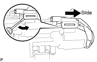
| 2. REMOVE TRANSPONDER KEY AMPLIFIER |
Disengage the 2 claws and slide the transponder key amplifier in the direction shown in the illustration, to detach it from the steering column upper with switch bracket assembly.
| 3. REMOVE STEERING COLUMN UPPER WITH SWITCH BRACKET ASSEMBLY |
Fix the steering column assembly in a vise between aluminum plates.
- NOTICE:
- Do not overtighten the vise.
Using a drill, drill a hole in each of the 2 steering lock set bolts, to insert an screw extractor.
Using the screw extractor, remove the 2 steering lock set bolts and remove the steering column upper with switch bracket assembly and steering column clamp upper.
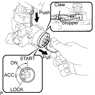
| 4. REMOVE IGNITION SWITCH LOCK CYLINDER ASSEMBLY |
Turn the ignition switch to on (ACC).
Insert the tip of a screwdriver into the hole in the steering column bracket assembly upper, as shown in the illustration, and pull the ignition switch lock cylinder assembly out until its claw comes into contact with the stopper of the steering column bracket assembly upper.
- NOTICE:
- Pull the ignition switch lock cylinder assembly out until its claw comes into contact with the stopper of the steering column bracket assembly upper. Otherwise, the following procedure cannot be conducted properly.
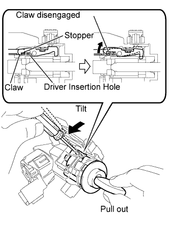
Insert the tip of a screwdriver into the hole in the steering column bracket and tilt it downward, as shown in the illustration, to disengage the claw of the ignition switch lock cylinder. Then pull out the ignition switch lock cylinder.
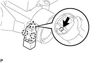
| 5. REMOVE UN-LOCK WARNING SWITCH ASSEMBLY |
Push up the unlock warning switch assembly center portion to disengage the 2 claws.
- HINT:
- Slide the unlock warning switch assembly, in the direction shown by the arrow in the illustration, to remove it.
| 6. REMOVE KEY INTER LOCK SOLENOID |
for Automtic Transaxle:
Remove the 2 screws and remove the key lock solenoid from the steering column bracket assembly upper.
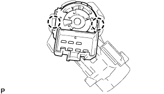
| 7. REMOVE IGNITION OR STARTER SWITCH ASSEMBLY |
Disengage the 2 claws and remove the ignition (starter) switch assembly from the steering column bracket assembly upper.