INSTALL BRAKE MASTER CYLINDER SUB-ASSEMBLY (for ABS with VSC)
INSTALL BRAKE MASTER CYLINDER SUB-ASSEMBLY (for ABS without VSC)
Brake Booster (For Sedan) -- Installation |
| 1. INSTALL BRAKE VACUUM CHECK VALVE ASSEMBLY |
 |
Install the grommet onto the brake booster.
Install the vacuum check valve onto the brake booster.
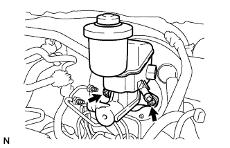
| 2. INSTALL BRAKE BOOSTER |
Provisionally install the push rod clevis onto the brake booster.
- HINT:
- Tighten the push rod lock nut when adjusting the brake pedal height.
Install a new gasket onto the brake booster.
Install the brake booster with the 4 nuts.
- Torque:
- 9.0 N*m{92 kgf*cm, 80 in.*lbf}
 |
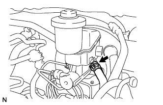
Connect the vacuum hose to the vacuum check valve with the clip.
 |
| 3. INSTALL FRONT BRAKE TUBE (w/o ABS) |
Using a union nut wrench, install the brake tube assembly onto the proportioning valve.
- Torque:
- 15 N*m{155 kgf*cm, 11 ft.*lbf}
- NOTICE:
- Use the formula to calculate special torque values for situations where a union nut wrench is combined with a torque wrench (YARIS_NCP93 RM000000UYX0BYX.html).
 |
Using a union nut wrench, install the 2 brake tubes onto the brake tube No. 1 way.
- Torque:
- 15 N*m{155 kgf*cm, 11 ft.*lbf}
- NOTICE:
- Use the formula to calculate special torque values for situations where a union nut wrench is combined with a torque wrench (YARIS_NCP93 RM000000UYX0BYX.html).
 |
| 4. INSTALL BRAKE MASTER CYLINDER PUSH ROD CLEVIS |
Apply lithium soap base glycol grease to the push rod pin.
Install the push rod clevis with the push rod pin and clip.
 |
Install the brake pedal return spring.
| 5. INSPECT AND ADJUST BRAKE BOOSTER PUSH ROD (w/ VSC) |
- NOTICE:
- Make an adjustment with no vacuum in the brake booster assembly. (Depress the brake pedal several times with the engine stopped.)
- HINT:
- Adjustment of the brake booster push rod is required when the brake master cylinder sub-assembly is replaced with a new one.
- Adjustment is not necessary when the removed brake master cylinder sub-assembly is reused and the brake booster assembly is replaced with a new one.
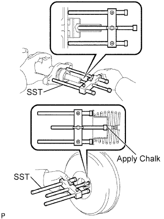
Apply chalk to the tip of the accessory tool.
- HINT:
- An accessory tool is enclosed with a new brake master cylinder sub-assembly.
Place the accessory tool on the brake booster assembly.
Text in Illustration *1 Accessory Tool
 |
Measure the clearance between the brake booster push rod and accessory tool.
- Standard clearance:
- 0 mm (0 in.)
- HINT:
- Adjust the clearance in the following cases:
- If there is a clearance between the accessory tool and the shell of the brake booster (floating accessory tool), the push rod is protruding too far.
- If the chalk does not stick on the tip of the brake booster push rod, the push rod protrusion is insufficient.
If the clearance is not as specified, adjust the push rod length by holding the rod using SST and turning the tip of the rod using a socket driver (7 mm).
- SST
- 09737-00020
- HINT:
- Check the push rod clearance again after adjustment.
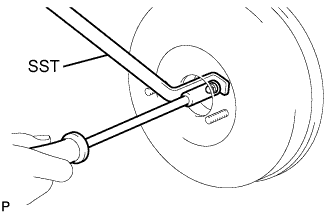 |
| 6. INSPECT AND ADJUST BRAKE BOOSTER PUSH ROD (w/o VSC) |
 |
Set SST on the master cylinder sub-assembly and lower the rod of SST until it just touches the piston.
- SST
- 09737-00013
- HINT:
- SST: 09737-00012 can also be used.
Apply chalk to the flat tip of the SST rod. Turn SST upside down and measure the clearance between the brake booster push rod and SST.
- Standard Clearance:
- -0.21 to 0 mm (-0.0083 to 0 in.)
If the clearance is not within the standard, adjust the length by holding the rod using SST and turning the tip of the rod using a 7 mm socket driver.
- SST
- 09737-00020
- NOTICE:
- Check the push rod clearance again after adjusting.
 |
| 7. INSTALL BRAKE MASTER CYLINDER SUB-ASSEMBLY (for ABS with VSC) |
Install a new O-ring onto the brake master cylinder sub-assembly.
Install the brake master cylinder sub-assembly and wire harness clamp bracket with the 2 nuts.
- Torque:
- 13 N*m{127 kgf*cm, 9 ft.*lbf}
 |
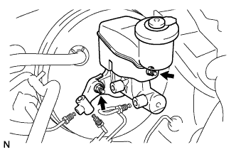
Using a union nut wrench (12 mm), install the 2 brake tubes onto the brake master cylinder subassembly.
- Torque:
- 20 N*m{199 kgf*cm, 14 ft.*lbf}
- NOTICE:
- Use the formula to calculate special torque values for situations where a union nut wrench is combined with a torque wrench (YARIS_NCP93 RM000000UYX0BYX.html).
 |
Connect the brake fluid level warning switch connector.
| 8. INSTALL BRAKE MASTER CYLINDER SUB-ASSEMBLY (for ABS without VSC) |
Install a new O-ring onto the brake master cylinder sub-assembly.
Install the brake master cylinder sub-assembly with the 2 nuts.
- Torque:
- 13 N*m{127 kgf*cm, 9 ft.*lbf}
 |
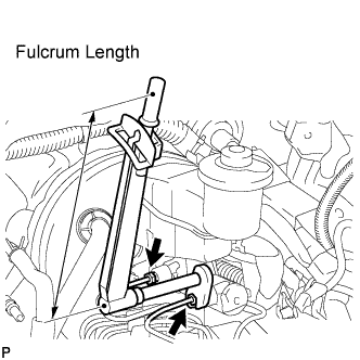
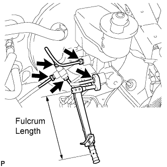
Using a union nut wrench, install the brake tubes onto the brake master cylinder sub-assembly.
- Torque:
- without union nut wrench:
- 15 N*m{155 kgf*cm, 11 ft.*lbf}
- with union nut wrench:
- 14 N*m{144 kgf*cm, 10 ft.*lbf}
- HINT:
- This torque value can be obtained by using a torque wrench with a fulcrum length of 300 mm (11.8 in.) and a union nut wrench with a fulcrum length of 22 mm (0.866 in.) (YARIS_NCP93 RM000000UYX0BYX.html).
- This torque value is effective when the union nut wrench is parallel to the torque wrench.
 |
Connect the brake fluid level warning switch connector.
| 9. INSTALL BRAKE MASTER CYLINDER SUB-ASSEMBLY (w/o ABS) |
Install a new O-ring onto the brake master cylinder sub-assembly.
Install the brake master cylinder sub-assembly and brake tube way with the 2 nuts.
- Torque:
- 13 N*m{127 kgf*cm, 9 ft.*lbf}
 |
Using a union nut wrench, install the brake tubes onto the brake master cylinder sub-assembly and brake tube way.
- Torque:
- without union nut wrench:
- 15 N*m{155 kgf*cm, 11 ft.*lbf}
- with union nut wrench:
- 14 N*m{144 kgf*cm, 10 ft.*lbf}
- HINT:
- This torque value can be obtained by using a torque wrench with a fulcrum length of 300 mm (11.8 in.) and a union nut wrench with a fulcrum length of 22 mm (0.866 in.) (YARIS_NCP93 RM000000UYX0BYX.html).
- This torque value is effective when the union nut wrench is parallel to the torque wrench.
 |
Connect the brake fluid level warning switch connector.
| 10. CONNECT CLUTCH RESERVOIR TUBE (for Manual Transaxle) |
 |
Connect the clutch reservoir tube with the clip.
| 11. INSTALL BRAKE ACTUATOR (w/ VSC) |
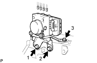
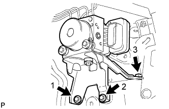
Install the brake actuator with bracket with the 3 bolts in the sequence shown in the illustration.
- Torque:
- 19 N*m{194 kgf*cm, 14 ft.*lbf}
- NOTICE:
- Do not damage the brake tubes or wire harness.
 |
Temporarily install each brake tube in the correct positions of the brake actuator as shown in the illustration.
Text in Illustration *a To front wheel cylinder RH *b To front wheel cylinder LH *c To rear wheel cylinder RH *d To rear wheel cylinder LH *e From 1st master cylinder *f From 2nd master cylinder
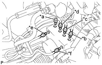 |
Using a union nut wrench 10 mm and a union nut wrench 12 mm, install the 6 brake tubes onto the brake actuator.
Text in Illustration 
Flare Nut 10 mm 
Flare Nut 12 mm - Torque:
- Flare Nut (M10):
- 15 N*m{155 kgf*cm, 11 ft.*lbf}
- Flare Nut (M12):
- 20 N*m{199 kgf*cm, 14 ft.*lbf}
- NOTICE:
- Use the formula to calculate special torque values for situations where a union nut wrench is combined with a torque wrench (YARIS_NCP93 RM000000UYX0BYX.html).
 |
Connect the brake actuator connector.
- NOTICE:
- Make sure that the connector is locked securely.
- Make sure that the actuator connector can be connected smoothly. Do not allow entry of water, oil or dirt.
 |
| 12. INSTALL BRAKE ACTUATOR (w/o VSC) |
Install the brake actuator with bracket with the 3 bolts in the sequence shown in the illustration.
- Torque:
- 19 N*m{194 kgf*cm, 14 ft.*lbf}
- NOTICE:
- Do not damage the brake tubes or wire harness.
 |
Temporarily install each brake tube in the correct positions of the brake actuator as shown in the illustration.
Text in Illustration *a To front wheel cylinder RH *b To front wheel cylinder LH *c To rear wheel cylinder RH *d To rear wheel cylinder LH *e From 1st master cylinder *f From 2nd master cylinder
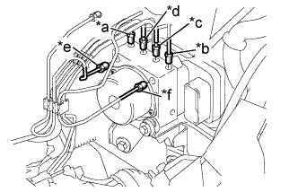 |
Using a union nut wrench 10 mm, install the 6 brake tubes onto the brake actuator.
- Torque:
- 15 N*m{155 kgf*cm, 11 ft.*lbf}
- NOTICE:
- Use the formula to calculate special torque values for situations where a union nut wrench is combined with a torque wrench (YARIS_NCP93 RM000000UYX0BYX.html).
Connect the brake actuator connector.
- NOTICE:
- Make sure that the connector is locked securely.
- Make sure that the actuator connector can be connected smoothly. Do not allow entry of water, oil or dirt.
|
| 13. INSTALL BATTERY CARRIER |
Install the battery carrier with the 5 bolts.
- Torque:
- 17 N*m{173 kgf*cm, 13 ft.*lbf}
Install the clamp.
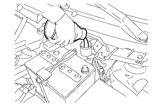
| 14. INSTALL BATTERY TRAY |
| 15. INSTALL BATTERY |
Install the battery onto the vehicle with the battery clamp.
- Torque:
- 3.5 N*m{36 kgf*cm, 31 in.*lbf}
Connect the cable to the battery terminal.
- Torque:
- 5.4 N*m{55 kgf*cm, 48 in.*lbf}
| 16. INSTALL LOWER INSTRUMENT PANEL FINISH PANEL SUB-ASSEMBLY |
 |
Install the 2 <A> screws.
Engage the 7 claws and install the instrument panel lower finish panel.
 |
| 17. INSTALL INSTRUMENT PANEL UNDER COVER SUB-ASSEMBLY |
Engage the 3 claws and install the instrument panel under cover.
 |
Tighten the 2 screws.
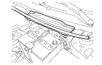
| 18. INSTALL OUTER COWL TOP PANEL |
Install the cowl top panel outer with the 8 bolts.
- Torque:
- 6.5 N*m{66 kgf*cm, 58 in.*lbf}
Install the cowl top to cowl inner brace with the 2 bolts.
- Torque:
- 6.5 N*m{66 kgf*cm, 58 in.*lbf}
Connect the wire harness clamp.
| 19. INSTALL FRONT AIR SHUTTER SEAL |
Engage the 3 claws to install the front air shutter seal RH.
| 20. INSTALL FRONT WIPER MOTOR AND LINK |
Connect the connector.
 |
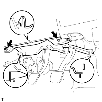
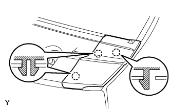
Slide the wiper link as shown in the illustration and engage the rubber pin with the body.
Install the front wiper motor and link with the 2 bolts.
- Torque:
- 5.5 N*m{56 kgf*cm, 49 in.*lbf}
| 21. INSTALL COWL TOP VENTILATOR LOUVER SUB-ASSEMBLY |
Connect the washer hoses.
 |
Engage the 5 hooks.
Engage the 8 hooks and the 4 claws.
 |
Install the cowl top ventilator louver sub-assembly with the 3 clips.
| 22. INSTALL COWL SIDE VENTILATOR SUB-ASSEMBLY LH |
Engage the 3 claws and install the cowl side ventilator sub-assembly LH.
 |
| 23. INSTALL COWL SIDE VENTILATOR SUB-ASSEMBLY RH |
- HINT:
- Use the same procedure as for the LH side.
| 24. INSTALL FRONT WIPER ARM AND BLADE ASSEMBLY LH |
Scrape any metal powder off the serrated part of the wiper arm with a round file or the equivalent (when reinstalling).
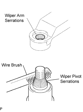 |
Clean the wiper pivot serrations with a wire brush.
Operate the wiper, then stop the windshield wiper motor in the automatic stop position.
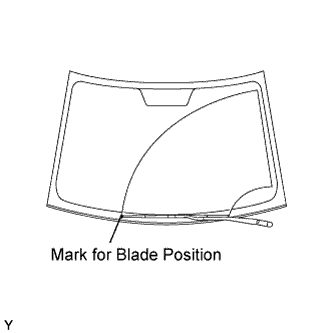
Align the blade tip with the mark on the windshield glass, as shown in the illustration.
 |
Tighten the nut of the front wiper arm.
- Torque:
- 26 N*m{265 kgf*cm, 19 ft.*lbf}
| 25. INSTALL FRONT WIPER ARM AND BLADE ASSEMBLY RH |
Scrape any metal powder off the serrated part of the wiper arm with a round file or the equivalent (when reinstalling).
|
Clean the wiper pivot serrations with a wire brush.
Operate the wiper, then stop the windshield wiper motor in the automatic stop position.
Align the blade tip with the mark on the windshield glass, as shown in the illustration.
 |
Tighten the nut of the front wiper arm.
- Torque:
- 26 N*m{265 kgf*cm, 19 ft.*lbf}
| 26. INSTALL FRONT WIPER ARM HEAD CAP |
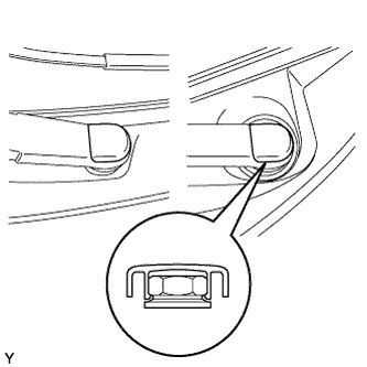
Engage the claw and install the 2 front wiper arm head caps.
 |
| 27. CONNECT CABLE TO NEGATIVE BATTERY TERMINAL |
- Torque:
- 5.4 N*m{55 kgf*cm, 48 in.*lbf}
| 28. FILL RESERVOIR WITH BRAKE FLUID |
 |
Disengage the 3 clips and separate the hood to cowl top seal.
Remove the cowl top ventilator louver.
Set the brake fluid can upside down on the reservoir.
- Fluid:
- SAE J1703 or FMVSS No. 116 DOT3
 |
| 29. BLEED MASTER CYLINDER |
- HINT:
- If the master cylinder has been disassembled or if the reservoir becomes empty, bleed the air from the master cylinder.
Using a union nut wrench, disconnect the brake tubes from the master cylinder.
 |
Slowly depress the brake pedal and hold it there (Step A).
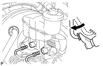 |
Block the outer holes with your fingers, and release the brake pedal (Step B).
 |
Repeat step A and B 3 or 4 times.
Using a union nut wrench, connect the brake tubes to the master cylinder.
- Torque:
- without union nut wrench:
- 15 N*m{155 kgf*cm, 11 ft.*lbf}
- with union nut wrench:
- 14 N*m{144 kgf*cm, 10 ft.*lbf}
- HINT:
- This torque value can be obtained by using a torque wrench with a fulcrum length of 300 mm (11.8 in.) and a union nut wrench with a fulcrum length of 22 mm (0.866 in.) (YARIS_NCP93 RM000000UYX0BYX.html).
- This torque value is effective when the union nut wrench is parallel to the torque wrench.
|
| 30. BLEED BRAKE LINE |
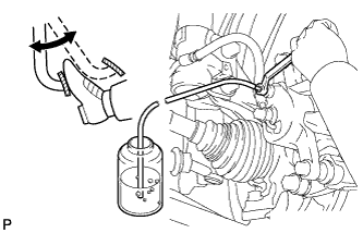 |
Connect the vinyl tube to the bleeder plug.
Depress the brake pedal several times, then loosen the bleeder plug with the pedal depressed (Step C).
At the point where the fluid stops coming out, tighten the bleeder plug, then release the brake pedal (Step D).
Repeat step C and D until all the air in the fluid is completely bled out.
Tighten the bleeder plug.
- Torque:
- 8.3 N*m{85 kgf*cm, 73 in.*lbf}
Repeat the above procedure to bleed the air out of the brake line for each wheel.
| 31. BLEED BRAKE ACTUATOR (w/ VSC) |
- NOTICE:
- After bleeding the air from the brake system, if the height or feel of the brake pedal cannot be obtained, perform air bleeding of the brake actuator with the Techstream by following the procedure below.
Depress the brake pedal more than 20 times with the engine off.
Connect the Techstream to the DLC3, and turn the ignition switch ON.
- NOTICE:
- Do not start the engine.
Select "Air Bleeding" on the Techstream.
- HINT:
- Refer to the tester operator's manual for further details.
Bleed the air out of the brake line when Step 1: Increase appears on the Techstream display.
- NOTICE:
- Bleed the air by following the steps displayed on the Techstream.
- Make sure that the master cylinder reservoir tank does not become empty.
Connect the vinyl tube to either one of the bleeder plugs.
Depress the brake pedal several times, then loosen the bleeder plug connected to the vinyl tube with the pedal depressed (Step E).
When fluid stops coming out, tighten the bleeder plug and release the brake pedal (Step F).
Repeat Steps E and F until all the air in the fluid is completely bled out.
Tighten the bleeder plug completely.
- Torque:
- Front brake:
- 8.3 N*m{85 kgf*cm, 73 in.*lbf}
- Torque:
- Rear brake:
- 8.5 N*m{87 kgf*cm, 75 in.*lbf}
Repeat the above procedure for each wheel to bleed the air out of the brake line.
Bleed the air out of the suction line when Step 2: Inhalation appears on the Techstream display.
- NOTICE:
- Bleed the air by following the steps displayed on the Techstream.
- Make sure that the master cylinder reservoir tank does not become empty.
Connect the vinyl tube to the bleeder plug at the right front wheel or the right rear wheel and loosen the bleeder plug.
Operate the brake actuator to bleed the air using the Techstream (Step G).
- NOTICE:
- Release the brake pedal at this time.
- HINT:
- This operation stops automatically after 4 seconds.
Check if the operation has stopped by referring to the Techstream display and tighten the bleeder plug (Step H).
Repeat Steps G and H until all the air in the fluid is completely bled out.
Tighten the bleeder plug.
- Torque:
- Front brake:
- 8.3 N*m{85 kgf*cm, 73 in.*lbf}
- Torque:
- Rear brake:
- 8.5 N*m{87 kgf*cm, 75 in.*lbf}
Repeat the above procedure for the other wheels to bleed the air out of the brake line.
Bleed the air out of the pressure reduction line when Step 3: Decrease appears on the Techstream display.
- NOTICE:
- Bleed the air by following the steps displayed on the Techstream.
- Make sure that the master cylinder reservoir tank does not become empty.
Connect a vinyl tube to either one of the bleeder plugs.
Loosen the bleeder plug (Step I).
Using the Techstream, operate the brake actuator assembly, completely depress the brake pedal and hold it there (Step J).
- NOTICE:
- During this procedure, the pedal will feel heavy, but completely depress it so that the brake fluid comes out of the bleeder plug.
- Hold the brake pedal depressed. Do not depress and release the pedal repeatedly.
- HINT:
- The operation stops automatically after 4 seconds. When performing this procedure continuously, set an interval of at least 20 seconds.
- When the operation is complete, the brake pedal goes down slightly. This is a normal phenomenon caused when the solenoid opens.
Tighten the bleeder plug, then release the brake pedal (Step K).
Repeat Steps I to K until all the air in the fluid is completely bled out.
Tighten the bleeder plug.
- Torque:
- Front brake:
- 8.3 N*m{85 kgf*cm, 73 in.*lbf}
- Torque:
- Rear brake:
- 8.5 N*m{87 kgf*cm, 75 in.*lbf}
Repeat the above procedure for the other wheels to bleed the air out of the brake line.
Bleed the air out of the brake line again when Step 4: Increase appears on the Techstream display.
- NOTICE:
- Bleed the air by following the steps displayed on the Techstream.
- Make sure that the master cylinder reservoir tank does not become empty.
Connect the vinyl tube to either one of the bleeder plugs.
Depress the brake pedal several times, then loosen the bleeder plug connected to the vinyl tube with the pedal depressed (Step L).
When fluid stops coming out, tighten the bleeder plug, then release the brake pedal (Step M).
Repeat Steps L and M until all the air in the fluid is completely bled out.
Tighten the bleeder plug.
- Torque:
- Front brake:
- 8.3 N*m{85 kgf*cm, 73 in.*lbf}
- Torque:
- Rear brake:
- 8.5 N*m{87 kgf*cm, 75 in.*lbf}
Repeat the above procedure for the other wheels to bleed the air out of the brake line.
Make sure that the air bleeding is complete by referring to the Techstream display and turn off the Techstream.
Disconnect the Techstream from the DLC3.
Turn the ignition switch OFF.
| 32. CHECK FLUID LEVEL IN RESERVOIR |
Check the fluid level and add fluid if necessary.
- Fluid:
- SAE J1703 or FMVSS No. 116 DOT3
| 33. INSPECT FOR BRAKE FLUID LEAK |
| 34. INSPECT AND ADJUST BRAKE PEDAL |
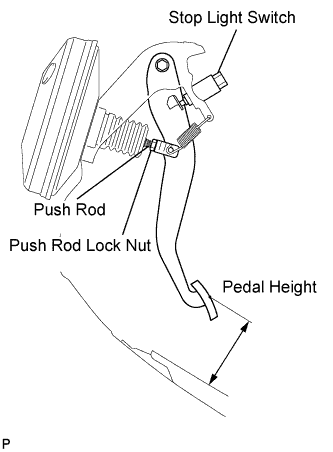 |
Inspect the brake pedal height.
- Pedal height from floor:
w/ ABS w/o ABS 113.1 to 123.1 mm
(4.45 to 4.85 in.)107.8 to 117.8 mm
(4.244 to 4.638 in.)
Adjust the brake pedal height.
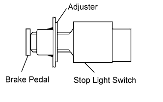
Disconnect the connector from the stop light switch.
Turn the stop light switch counterclockwise, and remove the stop light switch.
Loosen the push rod lock nut.
Adjust the pedal height by turning the pedal push rod.
- Pedal height from floor:
w/ ABS w/o ABS 113.1 to 123.1 mm
(4.45 to 4.85 in.)107.8 to 117.8 mm
(4.244 to 4.638 in.)
Tighten the push rod lock nut.
- Torque:
- 26 N*m{265 kgf*cm, 19 ft.*lbf}
Insert the stop light switch into the adjuster until it just touches the brake pedal.
- NOTICE:
- Do not depress the brake pedal.
Make a quarter turn clockwise to install the stop light switch.
- NOTICE:
- Do not depress the brake pedal.
- HINT:
- The turning torque for installing the stop light switch:
- Torque:
- 1.5 N*m{15 kgf*cm, 13 in.*lbf}or less
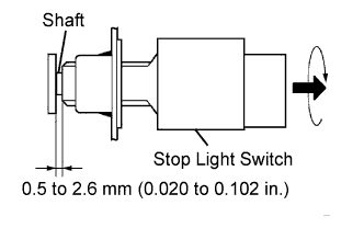
Check the stop light switch clearance.
- Stop light switch clearance:
- 0.5 to 2.6 mm (0.020 to 0.102 in.)
Connect the connector to the stop light switch.
Inspect the brake pedal free play.
Stop the engine and depress the brake pedal several times until there is no vacuum left in the booster.
Push in the pedal until the beginning of the resistance is felt. Measure the distance as shown.
- Pedal free play:
- 1.0 to 6.0 mm (0.039 to 0.236 in.)
 |
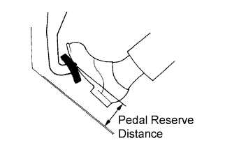
Inspect the brake pedal reserve distance.
Release the parking brake lever. With the engine running, depress the pedal and measure the pedal reserve distance as shown.
- Pedal reserve distance from floor at 294 N (30 kgf, 66.1 lbf):
for ABS with VSC for ABS without VSC w/o ABS More than 76 mm (2.99 in.) More than 73 mm (2.87 in.) More than 70 mm (2.75 in.)
- HINT:
- Sound and resistance from the brake booster when the brake pedal is depressed without a vacuum does not indicate a problem.
 |