Vehicle Stability Control System (For Hatchback With Separate Type Yaw Rate Sensor) Ts And Cg Terminal Circuit
DESCRIPTION
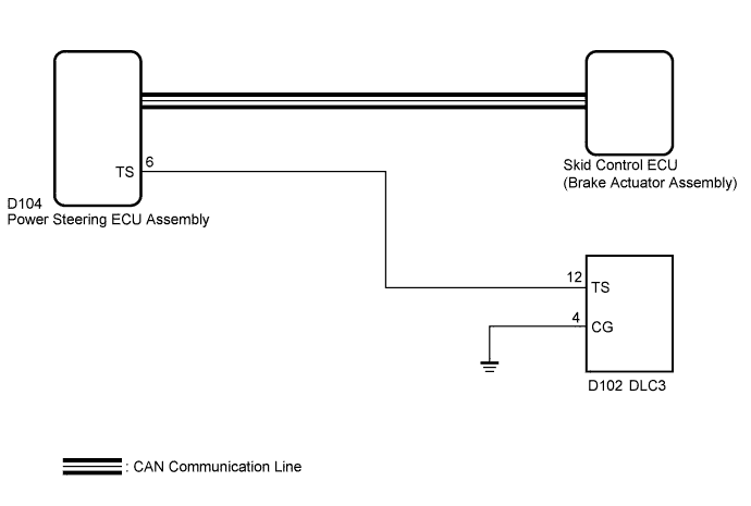
WIRING DIAGRAM
INSPECTION PROCEDURE
CHECK CAN COMMUNICATION SYSTEM
INSPECT DLC3
CHECK HARNESS AND CONNECTOR (TS of DLC3 - POWER STEERING ECU ASSEMBLY)
CHECK HARNESS AND CONNECTOR (CG of DLC3 - BODY GROUND)
INSPECT POWER STEERING ECU ASSEMBLY
VEHICLE STABILITY CONTROL SYSTEM (for Hatchback with Separate Type Yaw Rate Sensor) - TS and CG Terminal Circuit |
DESCRIPTION
In Test Mode (signal check), a malfunction in the speed sensor that cannot be detected when the vehicle is stopped can be detected while driving.Sensor check mode can be entered by connecting terminals TS and CG of the DLC3 and turning the ignition switch from off to ON.
WIRING DIAGRAM
INSPECTION PROCEDURE
- NOTICE:
- If the power steering ECU assembly or steering column assembly has been replaced, perform the torque sensor zero point calibration (YARIS_NCP93 RM000000XHR07EX.html).
| 1.CHECK CAN COMMUNICATION SYSTEM |
Check if CAN communication system DTCs are output (YARIS_NCP93 RM000001RSW02LX.html).
ResultResult
| Proceed to
|
DTC is not output
| A
|
DTC is output
| B
|
Turn the ignition switch to ON.
Measure the voltage according to the value(s) in the table below.
- Standard Voltage:
Tester Connection
| Switch Condition
| Specified Condition
|
D102-13 (TC) - D102-4 (CG)
| Ignition switch ON
| 11 to 14 V
|
ResultResult
| Proceed to
|
NG
| A
|
OK
| B
|
Text in Illustration*a
| Front view of DLC3
|
| 3.CHECK HARNESS AND CONNECTOR (TS of DLC3 - POWER STEERING ECU ASSEMBLY) |
Turn the ignition switch off.
Disconnect the power steering ECU connector.
Measure the resistance according to the value(s) in the table below.
- Standard Resistance:
Tester Connection
| Condition
| Specified Condition
|
D102-12 (TS) - D104-6 (TS)
| Always
| Below 1 Ω
|
D102-12 (TS) - Body ground
| Always
| 10 kΩ or higher
|
Reconnect the power steering ECU connector.
| | REPAIR OR REPLACE HARNESS OR CONNECTOR |
|
|
| 4.CHECK HARNESS AND CONNECTOR (CG of DLC3 - BODY GROUND) |
Measure the resistance according to the value(s) in the table below.
- Standard Resistance:
Tester Connection
| Condition
| Specified Condition
|
D102-4 (CG) - Body ground
| Always
| Below 1 Ω
|
| | REPAIR OR REPLACE HARNESS OR CONNECTOR |
|
|
| 5.INSPECT POWER STEERING ECU ASSEMBLY |
Turn the ignition switch off.
Using SST, connect terminals TS and CG of the DLC3.
Turn the ignition switch to ON.
Check that the PS warning light is blinking.
Text in Illustration*a
| Front view of DLC3
|
ResultResult
| Proceed to
|
The PS warning light is not blinking
| A
|
The PS warning light is blinking
| B
|