Dtc C1381 Acceleration Sensor Power Supply Voltage Malfunction
DESCRIPTION
WIRING DIAGRAM
INSPECTION PROCEDURE
INSPECT YAW RATE AND ACCELERATION SENSOR (IG TERMINAL)
INSPECT YAW RATE AND ACCELERATION SENSOR (GND TERMINAL)
RECONFIRM DTC
DTC C1381 Acceleration Sensor Power Supply Voltage Malfunction |
DESCRIPTION
The skid control ECU receives signals from the yaw rate and acceleration sensor via the CAN communication system.The yaw rate sensor has a built in acceleration sensor and detects the vehicle's condition using 2 circuits (GL1, GL2).If there is trouble in the bus lines between the yaw rate and acceleration sensor and the CAN communication system, the DTCs U0123 (malfunction in CAN communication with the yaw rate sensor) and U0124 (malfunction in CAN communication with the acceleration sensor) are output.These DTCs are also output when calibration has not been completed.DTC Code
| DTC Detection Condition
| Trouble Area
|
C1381
| At a vehicle speed of more than 3 km/h (2 mph), the acceleration sensor power source malfunction signal is received for 10 seconds or more.
| - Yaw rate and acceleration sensor
- Yaw rate and acceleration sensor power source circuit
|
WIRING DIAGRAM
Refer to DTCs C1232, C1243 and C1245 (YARIS_NCP93 RM000001RFV0AMX.html).
INSPECTION PROCEDURE
- NOTICE:
- When replacing the yaw rate and deceleration sensor, perform zero point calibration (YARIS_NCP93 RM000000XHR06QX.html).
- Inspect the fuses for circuits related to this system before performing the following inspection procedure.
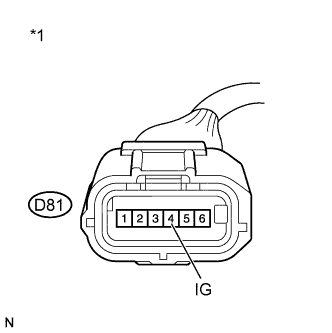
| 1.INSPECT YAW RATE AND ACCELERATION SENSOR (IG TERMINAL) |
Disconnect the yaw rate and acceleration sensor connector.
Text in Illustration*1
| Front view of wire harness connector
(to Yaw Rate and Acceleration Sensor)
|
Turn the ignition switch to ON.
Measure the voltage according to the value(s) in the table below.
- Standard Voltage:
Tester Connection
| Switch Condition
| Specified Condition
|
D81-4 (IG) - Body ground
| Ignition switch ON
| 11 to 14 V
|
| | REPAIR OR REPLACE HARNESS OR CONNECTOR (IG CIRCUIT) |
|
|
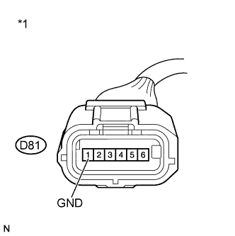
| 2.INSPECT YAW RATE AND ACCELERATION SENSOR (GND TERMINAL) |
Turn the ignition switch off.
Text in Illustration*1
| Front view of wire harness connector
(to Yaw Rate and Acceleration Sensor)
|
Measure the resistance according to the value(s) in the table below.
- Standard Resistance:
Tester Connection
| Condition
| Specified Condition
|
D81-1 (GND) - Body ground
| Always
| Below 1 Ω
|
- NOTICE:
- Check the yaw rate and acceleration sensor signal after replacement (YARIS_NCP93 RM000000XHT08IX.html).
- HINT:
- If troubleshooting has been carried out according to the Problem Symptoms Table, refer back to the table and proceed to the next step (YARIS_NCP93 RM000000XHN0AXX.html).
| | REPAIR OR REPLACE HARNESS OR CONNECTOR (GND CIRCUIT) |
|
|
Reconnect the yaw rate and acceleration sensor connector.
Clear the DTC (YARIS_NCP93 RM000000XHV0BQX.html).
Start the engine.
Perform a road test.
Check if the same DTC is recorded (YARIS_NCP93 RM000000XHV0BQX.html).
ResultResult
| Proceed to
|
DTC (C1381) is not output
| A
|
DTC (C1381) is output
| B
|