INSTALL STARTER ASSEMBLY (for Cold Area Specification Vehicles)
INSTALL STARTER ASSEMBLY (except Cold Area Specification Vehicles)
Automatic Transaxle Assembly (For Hatchback) -- Installation |
| 1. INSTALL WIRE HARNESS CLAMP BRACKET |
Install the 3 wire harness clamp brackets with the 3 bolts.
- Torque:
- 5.0 N*m{51 kgf*cm, 44 in.*lbf}
| 2. INSTALL TRANSMISSION OIL FILLER TUBE SUB-ASSEMBLY |
Apply Toyota Genuine ATF WS to a new O-ring, and install it to the transmission oil filler tube sub-assembly.
Install the transmission oil filler tube sub-assembly to the automatic transaxle assembly with the bolt.
- Torque:
- 5.5 N*m{56 kgf*cm, 49 in.*lbf}
Connect the breather hose to the transmission oil filler tube sub-assembly.
| 3. INSTALL TRANSMISSION OIL LEVEL DIPSTICK SUB-ASSEMBLY |
Install the transmission oil level dipstick sub-assembly into the transmission oil filler tube sub-assembly.
| 4. INSTALL NO. 2 OIL COOLER TUBE CLAMP |
Temporarily install the outlet No. 1 oil cooler tube to the oil cooler tube union.
Temporarily install the inlet No. 1 oil cooler tube to the oil cooler tube union.
Install the No. 2 oil cooler tube clamp to the transmission oil filler tube sub-assembly with the bolt.
- Torque:
- 5.5 N*m{56 kgf*cm, 49 in.*lbf}
| 5. CONNECT OUTLET NO. 1 OIL COOLER TUBE |
Using a union nut wrench 14 mm, connect the outlet No. 1 oil cooler tube while holding the oil cooler tube union with a wrench.
Text in Illustration *1 Union Nut Wrench 14 mm *a Hold *b Turn - Torque:
- 34 N*m{347 kgf*cm, 25 ft.*lbf}
- NOTICE:
- Use the formula to calculate special torque values for situations where the union nut wrench is combined with a torque wrench (YARIS_NCP93 RM00000482L007X.html).
 |
| 6. CONNECT INLET NO. 1 OIL COOLER TUBE |
Using a union nut wrench 14 mm, connect the inlet No. 1 oil cooler tube while holding the oil cooler tube union with a wrench.
Text in Illustration *1 Union Nut Wrench 14 mm *a Turn *b Hold - Torque:
- 34 N*m{347 kgf*cm, 25 ft.*lbf}
- NOTICE:
- Use the formula to calculate special torque values for situations where the union nut wrench is combined with a torque wrench (YARIS_NCP93 RM00000482L007X.html).
 |
| 7. INSTALL NO. 1 TRANSMISSION CONTROL CABLE BRACKET |
Install the No. 1 transmission control cable bracket to the automatic transaxle assembly with the 2 bolts.
- Torque:
- 12 N*m{122 kgf*cm, 9 ft.*lbf}
| 8. INSTALL SPEEDOMETER DRIVEN HOLE COVER SUB-ASSEMBLY |
Apply Toyota Genuine ATF WS to a new O-ring, and install it to the speedometer driven hole cover.
Install the speedometer driven hole cover sub-assembly to the automatic transaxle assembly.
- Torque:
- 7.0 N*m{71 kgf*cm, 62 in.*lbf}
| 9. INSPECT TORQUE CONVERTER ASSEMBLY |
Inspect the one-way clutch.
Press on the splines of the stator with a finger and rotate the stator. Check that the stator rotates smoothly when turned clockwise and rotates with difficulty when turned counterclockwise.
If necessary, clean the torque converter assembly and recheck the one-way clutch.
Replace the torque converter assembly if the one-way clutch still fails the inspection.Text in Illustration 
Difficult 
Smooth

Inspect the torque converter assembly.
If any of the following problems are present, replace the torque converter assembly.Text in Illustration *a Sample showing maximum allowable amount of powder in ATF - A metallic sound is emitted from the torque converter assembly during the stall test or when the shift lever is moved to N.
- The one-way clutch turns smoothly or locks in both directions.
- The amount of powder in the ATF is more than the sample shown in the illustration (refer to the sample).
- HINT:
- The sample shows approximately 0.025 liters (0.026 US qts, 0.022 Imp. qts) of ATF that was removed from a torque converter assembly.
- A metallic sound is emitted from the torque converter assembly during the stall test or when the shift lever is moved to N.
 |
Replace the ATF in the torque converter assembly.
- HINT:
- If the ATF is discolored or has a foul odor, stir the ATF in the torque converter assembly before replacing the ATF.
Clean and check the oil cooler and oil pipe line.
- HINT:
- If the torque converter assembly is inspected or the ATF is replaced, it is necessary to clean the oil cooler and oil pipe line.
- Apply compressed air of 196 kPa (2.0 kgf/cm2, 28 psi) into the inlet hose.
- If a large amount of powder is found in the ATF, add new ATF using a bucket pump and clean the oil cooler and oil pipe line again.
- If the ATF is cloudy, inspect the oil cooler.
 |
Prevent deformation of the torque converter assembly and damage to the oil pump gear.
- NOTICE:
- Make sure that all of the bolts are the same length and that the specified bolts are used.
Text in Illustration *a Correct *b Incorrect *c Bottom is damaged - HINT:
- If there is any damage to the tip of a bolt for the torque converter assembly or to the bottom of a bolt hole, replace the bolt and torque converter assembly.
 |
| 10. INSTALL TORQUE CONVERTER ASSEMBLY |
Engage the splines of the input shaft and turbine runner.
 |
Engage the splines of the stator shaft and the stator while turning the torque converter assembly.
- HINT:
- If the stator shaft splines are difficult to engage with the stator splines, move the torque converter back approximately 10 mm (0.394 in.) and engage the splines while rotating the torque converter assembly.
 |
Turn the torque converter assembly to insert the key of the oil pump drive gear into the groove of the torque converter assembly.
 |
Clean the torque converter setting bolt holes.
Using a vernier caliper and straightedge, measure dimension A between the transaxle contact surface of the engine and the torque converter contact surface of the drive plate.
Text in Illustration *1 Engine Surface *2 Drive Plate Surface
 |
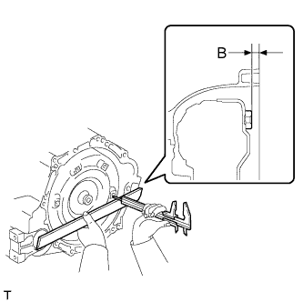
Using a vernier caliper and straightedge, measure dimension B shown in the illustration and check that dimension B is more than dimension A, which was measured in the previous step.
- Standard:
- B = A + 1 mm (0.0394 in.) or more
- NOTICE:
- Make sure to deduct the thickness of the straightedge.
- If the transaxle is installed to the engine with the torque converter not sufficiently inserted, the torque converter may be damaged.
- Do not include the thickness of the set block.
 |
| 11. INSTALL AUTOMATIC TRANSAXLE ASSEMBLY |
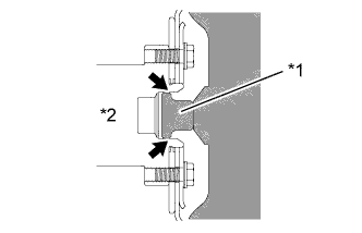
Apply clutch spline grease to the round of the crankshaft contact surface with the torque converter centerpiece.
Text in Illustration *1 Torque Converter Centerpiece *2 Crankshaft Clutch spline grease - Grease:
- Toyota Genuine Clutch Spline Grease or equivalent
- Maximum spread:
- Approximately 1 g (0.0353 oz)
 |
Confirm that 2 knock pins are on the transaxle contact surface of the engine cylinder block before transaxle installation.
Text in Illustration *1 Knock Pin
 |
Keeping the engine assembly and the automatic transaxle assembly in a horizontal position, align the knock pins with each hole on the automatic transaxle assembly and tighten the 7 bolts.
- Torque:
- 30 N*m{301 kgf*cm, 22 ft.*lbf}
- NOTICE:
- Confirm that the 2 knock pins are installed to the transaxle contact surface of the engine cylinder block before installing the transaxle.
- Do not forcibly pry on the automatic transaxle assembly.
- Check that the torque converter assembly rotates.
| 12. INSTALL TORQUE CONVERTER SETTING BOLT |
Remove any adhesive remaining in the 6 torque converter setting bolts.
 |
Apply adhesive to 2 or 3 threads on the end of the 6 torque converter setting bolts.
- Adhesive:
- Toyota Genuine Adhesive 1324, Three Bond 1324 or equivalent
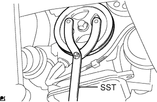
Use SST to hold the crankshaft pulley in place.
- SST
- 09960-10010(09962-01000,09963-01000)
 |
Install the 6 torque converter setting bolts.
- Torque:
- 28 N*m{286 kgf*cm, 21 ft.*lbf}
| 13. INSTALL FLYWHEEL HOUSING UNDER COVER |
Install the flywheel housing under cover.
| 14. INSTALL ENGINE MOUNTING BRACKET LH |
Clean and degrease the bolt and the bolt installation hole.
|
Apply adhesive to 2 or 3 threads on the end of the 4 bolts.
- Adhesive:
- Toyota Genuine Adhesive 1324, Three Bond 1324 or equivalent
Install the engine mounting bracket LH to the automatic transaxle assembly with the 4 bolts.
- Torque:
- 64 N*m{653 kgf*cm, 47 ft.*lbf}
Install the engine mounting insulator LH to the engine mounting bracket LH with the bolt and nut.
- Torque:
- 52 N*m{530 kgf*cm, 38 ft.*lbf}
- NOTICE:
- Turn the bolt while holding the nut.
| 15. INSTALL ENGINE MOVING CONTROL ROD BRACKET |
Install the engine moving control rod bracket to the automatic transaxle assembly with the 3 bolts.
- Torque:
- 45 N*m{459 kgf*cm, 33 ft.*lbf}
| 16. INSTALL FRONT SUSPENSION CROSSMEMBER SUB-ASSEMBLY |
| 17. INSTALL FRONT DRIVE SHAFT ASSEMBLIES |
| 18. CONNECT OUTLET OIL COOLER HOSE |
Connect the oil cooler outlet hose with the clip.
| 19. CONNECT INLET OIL COOLER HOSE |
Connect the oil cooler inlet hose with the clip.
| 20. INSTALL WIRE HARNESS |
Engage the 7 clamps and install the wire harness.
Connect the transmission revolution sensor connector.
Connect the transmission wire connector.
Connect the park/neutral position switch connector.
Install the No. 3 engine wire to the automatic transaxle assembly with the bolt.
- Torque:
- 26 N*m{260 kgf*cm, 19 ft.*lbf}
| 21. INSTALL TRANSMISSION CONTROL CABLE ASSEMBLY |
 |
Install the transmission control cable assembly to the control shaft lever with the nut.
- Torque:
- 12 N*m{122 kgf*cm, 9 ft.*lbf}
Text in Illustration *1 No. 1 Transmission Control Cable Bracket *2 Clip *a Marking
Install the transmission control cable assembly to the No. 1 transmission control cable bracket with a new clip.
- NOTICE:
- Make sure that the marking on the cable is aligned with the slit in the No. 1 transmission control cable bracket before installing the cable.
| 22. INSTALL STARTER ASSEMBLY (for Cold Area Specification Vehicles) |
| 23. INSTALL STARTER ASSEMBLY (except Cold Area Specification Vehicles) |
| 24. INSTALL AIR CLEANER BRACKET |
Install the air cleaner bracket with the 2 bolts.
- Torque:
- 20 N*m{199 kgf*cm, 14 ft.*lbf}
Engage the clamp and connect the wire harness to the air cleaner bracket.
| 25. INSTALL AIR CLEANER ASSEMBLY |
Install the air cleaner case onto the air cleaner bracket with the 2 bolts.
- Torque:
- 7.8 N*m{80 kgf*cm, 69 in.*lbf}
Engage the clamp and connect the wire harness to the air cleaner case.
Install the air cleaner element onto the air cleaner case.
Install the air cleaner cap sub-assembly with No. 1 air cleaner hose onto the throttle body assembly
Engage the 2 clamps and connect the air cleaner cap sub-assembly to the air cleaner case sub-assembly.
Tighten the hose clamp.
- Torque:
- 3.0 N*m{31 kgf*cm, 27 in.*lbf}
Connect the vacuum switching valve assembly connector.
Connect the mass air flow meter connector.
Engage the 2 clamps and connect the wire harness to the air cleaner cap sub-assembly and vacuum switching valve assembly.
Connect the No. 2 fuel vapor feed hose to the intake manifold.
Connect the fuel vapor feed hose assembly to the No. 1 air cleaner hose and vacuum switching valve assembly with the 2 hose clamps.
Engage the clamp and connect the fuel vapor feed hose assembly to the No. 1 air cleaner hose.
| 26. INSTALL BATTERY CARRIER |
Install the battery carrier with the 5 bolts.
- Torque:
- 17 N*m{173 kgf*cm, 13 ft.*lbf}
Engage the 6 clamps and connect the wire harness to the battery carrier.
| 27. INSTALL BATTERY TRAY |
| 28. INSTALL BATTERY |
Install the battery onto the battery tray with the battery clamp.
- Torque:
- 3.5 N*m{36 kgf*cm, 31 in.*lbf}
Connect the cable to the battery terminal.
- Torque:
- 5.4 N*m{55 kgf*cm, 48 in.*lbf}
| 29. ADD AUTOMATIC TRANSAXLE FLUID |
- Automatic Transaxle Fluid:
Classification Capacity
(Reference)Toyota Genuine ATF WS Dry fill 6.4 liters (6.8 US qts, 5.6 Imp. qts) Drain and refill 2.5 liters (2.6 US qts, 2.2 Imp. qts)
| 30. INSPECT AUTOMATIC TRANSAXLE FLUID |
 |
- HINT:
- Drive the vehicle until the engine and transaxle are at normal operating temperature.
- Fluid temperature:
- 70 to 80 °C (158 to 176 °F)
| *a | OK if hot |
| *b | Add if hot |
Park the vehicle on a level surface and engage the parking brake.
With the engine idling and the brake pedal depressed, shift the shift lever into all positions from P to L, and then return it to the P.
Pull out the oil level dipstick and wipe it clean.
Push it fully back into the pipe.
Pull it out and check that the fluid level is within the HOT range.
If there is any leakage, repair or replace O-rings, seal packing, oil seals, plugs or other parts.
| 31. INSPECT FOR AUTOMATIC TRANSAXLE FLUID LEAK |
| 32. ADJUST SHIFT LEVER POSITION |
Move the shift lever to N.
Slide the adjuster case cover in the direction shown by the arrow.
Text in Illustration *1 Adjuster Case *2 Cover *3 Lock Piece
 |
Using a precision screwdriver, pull up the lock piece.
Press the lock piece into the adjuster case.
Text in Illustration *1 Adjuster Case *2 Lock Piece *3 Cable Rod *4 Cover - HINT:
- Lightly pull the cable rod towards the back of the vehicle to eliminate slack, and then lock the adjuster.
 |
Slide the adjuster case cover in the direction shown by the arrow.
- NOTICE:
- If the cover is not pushed over the protrusion on the lock, the cable will not lock and shift operation will not be accurate.
| 33. INSPECT SHIFT LEVER POSITION |
Turn the ignition switch to ON and step on the brake pedal.
Confirm that the shift lever moves smoothly through all of the shift positions and the position indicator shows the correct shift lever position.
Start the engine and confirm that the vehicle moves forward when the shift lever is moved from N to D.
| 34. INSTALL REAR CONSOLE BOX ASSEMBLY |
| 35. RESET MEMORY (AT initialization) |
Perform Reset Memory (AT initialization) when replacing the automatic transaxle assembly (YARIS_NCP93 RM000000W7F0J7X.html).