Exhaust Manifold (For Sedan) Installation
INSTALL EXHAUST MANIFOLD
INSTALL MANIFOLD SUPPORT BRACKET
INSTALL NO. 1 EXHAUST MANIFOLD HEAT INSULATOR
INSTALL FRONT EXHAUST PIPE ASSEMBLY
INSTALL EXHAUST TAIL PIPE ASSEMBLY
INSTALL HEATED OXYGEN SENSOR
INSTALL OUTER COWL TOP PANEL
INSTALL FRONT AIR SHUTTER SEAL
INSTALL FRONT WIPER MOTOR AND LINK
INSTALL COWL TOP VENTILATOR LOUVER SUB-ASSEMBLY
INSTALL COWL SIDE VENTILATOR SUB-ASSEMBLY LH
INSTALL COWL SIDE VENTILATOR SUB-ASSEMBLY RH
INSTALL FRONT WIPER ARM AND BLADE ASSEMBLY LH
INSTALL FRONT WIPER ARM AND BLADE ASSEMBLY RH
REMOVE FRONT WIPER ARM HEAD CAP
INSTALL LOWER INSTRUMENT PAD LH
INSTALL CONSOLE BOX ASSEMBLY
INSTALL CONSOLE BOX CARPET
INSTALL CONSOLE BOX UPPER REAR PANEL SUB-ASSEMBLY
INSTALL CONSOLE BOX UPPER PANEL SUB-ASSEMBLY
INSTALL SHIFT LEVER KNOB SUB-ASSEMBLY (for Manual Transaxle)
INSTALL INSTRUMENT PANEL FINISH PANEL END LH
INSTALL INSTRUMENT PANEL LOWER CENTER FINISH PANEL
INSPECT FOR EXHAUST GAS LEAK
Exhaust Manifold (For Sedan) -- Installation |
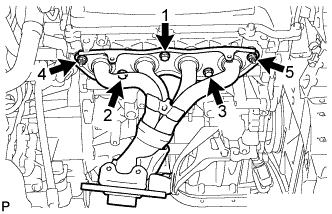
| 1. INSTALL EXHAUST MANIFOLD |
Tighten the nuts and bolts on the exhaust manifold, in the order shown in the illustration, through a new gasket.
- Torque:
- 27 N*m{275 kgf*cm, 20 ft.*lbf}
| 2. INSTALL MANIFOLD SUPPORT BRACKET |
Install the manifold support bracket with the 3 bolts.
- Torque:
- 44 N*m{449 kgf*cm, 33 ft.*lbf}
| 3. INSTALL NO. 1 EXHAUST MANIFOLD HEAT INSULATOR |
Install the No. 1 exhaust manifold heat insulator with the 4 bolts.
- Torque:
- 8.0 N*m{82 kgf*cm, 71 in.*lbf}
| 4. INSTALL FRONT EXHAUST PIPE ASSEMBLY |
Using vernier calipers, measure the free length of the compression spring.
- Minimum length (Front side):
- 40.5 mm (1.594 in.)
- Minimum length (Rear side):
- 38.5 (1.516 in.)
If the length is not as specified, replace the compression spring.
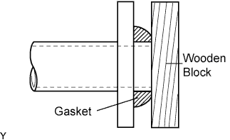
Using a plastic hammer and a wooden block, tap in a new exhaust pipe gasket until its surface is flush with the front exhaust pipe assembly.
- NOTICE:
- Install the exhaust pipe gasket in the correct direction.
- Do not damage the outer surface of the exhaust pipe gasket.
- Do not reuse the exhaust pipe gasket.
- Do not push in the gasket with the exhaust pipe when connecting it.
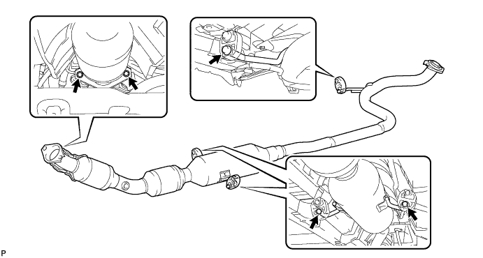
Install the 3 No. 4 exhaust pipe supports and front exhaust pipe assembly.
Install the exhaust front pipe assembly and a new exhaust pipe gasket with the 4 compression springs and 4 bolts.
- Torque:
- 43 N*m{438 kgf*cm, 32 ft.*lbf}
| 5. INSTALL EXHAUST TAIL PIPE ASSEMBLY |
Check the No. 4 exhaust pipe supports.
- NOTICE:
- Install No. 4 exhaust pipe support onto the pipe retaining support.
Install the 3 No. 4 exhaust pipe supports and the exhaust tail pipe assembly.
Install the 2 compression springs and 2 bolts.
- Torque:
- 43 N*m{438 kgf*cm, 32 ft.*lbf}
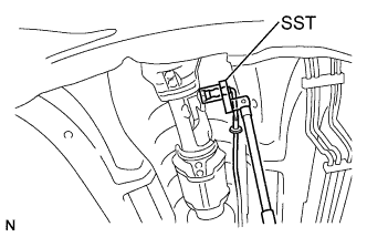
| 6. INSTALL HEATED OXYGEN SENSOR |
Using SST, install the heated oxygen sensor onto the front exhaust pipe.
- SST
- 09224-00010
- Torque:
- without SST:
- 44 N*m{449 kgf*cm, 32 ft.*lbf}
- with SST:
- 40 N*m{408 kgf*cm, 30 ft.*lbf}
- HINT:
- This torque value is effective when SST is parallel to the torque wrench.
- The "with SST" torque value is effective when using SST with a fulcrum length of 30 mm (1.18 in.).
- The "with SST" torque value is effective when using a torque wrench with a fulcrum length of 300 mm (11.81 in.).
- If using a torque wrench with a different length, or connecting the torque wrench and SST at an angle, refer to the alternate torque values (YARIS_NCP93 RM000000UYX0BYX.html).
Pass the sensor connector through the floor panel and install the grommet.
Connect the sensor connector.
| 7. INSTALL OUTER COWL TOP PANEL |
Install the cowl top panel outer with the 8 bolts.
- Torque:
- 6.5 N*m{66 kgf*cm, 58 in.*lbf}
Install the cowl top to cowl inner brace with the 2 bolts.
- Torque:
- 6.5 N*m{66 kgf*cm, 58 in.*lbf}
Connect the wire harness clamp.
| 8. INSTALL FRONT AIR SHUTTER SEAL |
Engage the 3 claws to install the front air shutter seal RH.
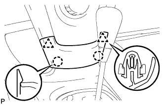
| 9. INSTALL FRONT WIPER MOTOR AND LINK |
Connect the connector.
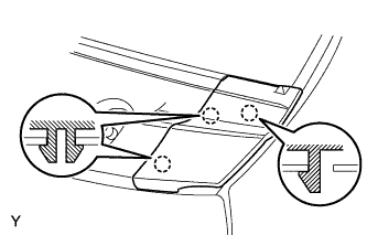
Slide the wiper link as shown in the illustration and engage the rubber pin with the body.
Install the front wiper motor and link with the 2 bolts.
- Torque:
- 5.5 N*m{56 kgf*cm, 49 in.*lbf}
| 10. INSTALL COWL TOP VENTILATOR LOUVER SUB-ASSEMBLY |
Connect the washer hoses.
Engage the 5 hooks.
Engage the 8 hooks and the 4 claws.
Install the cowl top ventilator louver sub-assembly with the 3 clips.
| 11. INSTALL COWL SIDE VENTILATOR SUB-ASSEMBLY LH |
Engage the 3 claws and install the cowl side ventilator sub-assembly LH.
| 12. INSTALL COWL SIDE VENTILATOR SUB-ASSEMBLY RH |
- HINT:
- Use the same procedure as for the LH side.
| 13. INSTALL FRONT WIPER ARM AND BLADE ASSEMBLY LH |
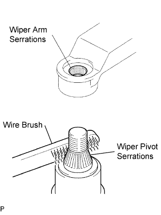
Scrape any metal powder off the serrated part of the wiper arm with a round file or the equivalent (when reinstalling).
Clean the wiper pivot serrations with a wire brush.
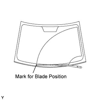
Operate the wiper, then stop the windshield wiper motor in the automatic stop position.
Align the blade tip with the mark on the windshield glass, as shown in the illustration.
Tighten the nut of the front wiper arm.
- Torque:
- 26 N*m{265 kgf*cm, 19 ft.*lbf}
| 14. INSTALL FRONT WIPER ARM AND BLADE ASSEMBLY RH |
Scrape any metal powder off the serrated part of the wiper arm with a round file or the equivalent (when reinstalling).
Clean the wiper pivot serrations with a wire brush.
Operate the wiper, then stop the windshield wiper motor in the automatic stop position.
Align the blade tip with the mark on the windshield glass, as shown in the illustration.
Tighten the nut of the front wiper arm.
- Torque:
- 26 N*m{265 kgf*cm, 19 ft.*lbf}
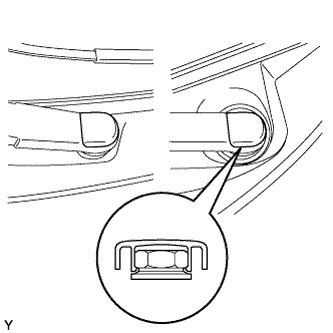
| 15. REMOVE FRONT WIPER ARM HEAD CAP |
Engage the claw and install the 2 front wiper arm head caps.
| 16. INSTALL LOWER INSTRUMENT PAD LH |
Engage the claw and 3 clips and install the instrument pad lower.
Install screw <I>.
| 17. INSTALL CONSOLE BOX ASSEMBLY |
Engage the 4 claws and install the rear console box.
Install the 2 bolts and 2 screws.
Connect the clamp.
| 18. INSTALL CONSOLE BOX CARPET |
Install the console box carpet.
| 19. INSTALL CONSOLE BOX UPPER REAR PANEL SUB-ASSEMBLY |
Connect the connector.
Engage the 3 clips and 3 claws and install the console upper rear panel.
| 20. INSTALL CONSOLE BOX UPPER PANEL SUB-ASSEMBLY |
Engage the 5 clips and the claw and install the upper console panel.
| 21. INSTALL SHIFT LEVER KNOB SUB-ASSEMBLY (for Manual Transaxle) |
Install the shift lever knob.
| 22. INSTALL INSTRUMENT PANEL FINISH PANEL END LH |
Engage the 6 claws and 3 clips and install the instrument panel finish panel end LH.
| 23. INSTALL INSTRUMENT PANEL LOWER CENTER FINISH PANEL |
Engage the 2 claws and 2 clips and install the instrument panel finish panel lower center.
| 24. INSPECT FOR EXHAUST GAS LEAK |