Engine Unit (For Sedan) Installation
INSTALL EXHAUST MANIFOLD
INSTALL MANIFOLD SUPPORT BRACKET
INSTALL NO. 1 EXHAUST MANIFOLD HEAT INSULATOR
INSTALL WIRE HARNESS CLAMP BRACKET
INSTALL ENGINE WIRE
INSTALL BOOSTER VACUUM TUBE
INSTALL NO. 1 WATER BY-PASS PIPE
INSTALL INTAKE MANIFOLD
INSTALL ENGINE OIL LEVEL DIPSTICK
INSTALL GENERATOR ASSEMBLY
INSTALL NO. 1 IGNITION COIL
INSTALL WATER FILLER SUB-ASSEMBLY
INSTALL FUEL TUBE SUB-ASSEMBLY
INSTALL VENTILATION HOSE
Engine Unit (For Sedan) -- Installation |
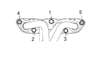
| 1. INSTALL EXHAUST MANIFOLD |
Install the exhaust manifold with the 3 bolts and 2 nuts, in the order shown in the illustration, through a new gasket.
- Torque:
- 27 N*m{275 kgf*cm, 20 ft.*lbf}
| 2. INSTALL MANIFOLD SUPPORT BRACKET |
Install the manifold bracket with the 3 bolts.
- Torque:
- 44 N*m{449 kgf*cm, 33 ft.*lbf}
| 3. INSTALL NO. 1 EXHAUST MANIFOLD HEAT INSULATOR |
Install the exhaust manifold insulator with the 4 bolts.
- Torque:
- 8.0 N*m{82 kgf*cm, 71 in.*lbf}
| 4. INSTALL WIRE HARNESS CLAMP BRACKET |
Install the 2 wire harness clamp brackets with the 2 bolts.
- Torque:
- 9.8 N*m{100 kgf*cm, 87 in.*lbf} bolt A
- 13 N*m{131 kgf*cm, 10 ft.*lbf} bolt B
Connect all sensor connectors and wire harness clamps to the engine assembly and install the engine wire harness.
| 6. INSTALL BOOSTER VACUUM TUBE |
Install the booster vacuum tube with the 2 bolts.
- Torque:
- 9.0 N*m{92 kgf*cm, 80 in.*lbf}
| 7. INSTALL NO. 1 WATER BY-PASS PIPE |
Install the No. 1 water bypass pipe through a new gasket with the 2 bolts and 2 nuts.
- Torque:
- 9.0 N*m{92 kgf*cm, 80 in.*lbf}
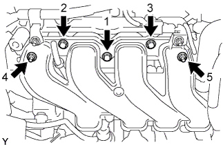
| 8. INSTALL INTAKE MANIFOLD |
Install a new gasket onto the intake manifold.
Provisionally tighten the intake manifold nuts and bolts in the order shown in the illustration, and then tighten them to the specified torque.
- Torque:
- 30 N*m{306 kgf*cm, 22 ft.*lbf}
Connect the water by-pass hose to the No. 1 water by-pass pipe.
Connect the water bypass hose to the cylinder head.
Connect the union to connector tube hose to the booster vacuum tube.
| 9. INSTALL ENGINE OIL LEVEL DIPSTICK |
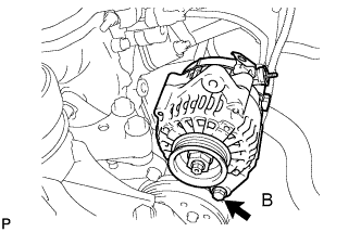
| 10. INSTALL GENERATOR ASSEMBLY |
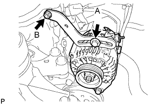
Provisionally install the generator with fixing bolt B.
Provisionally install the fan belt adjusting slider with fan belt adjusting slider fixing bolts A and B, then move the generator toward the cylinder block and tighten bolt B.
- Torque:
- 11 N*m{112 kgf*cm, 8.1 ft.*lbf}
Install the connector and the wire harness clamp.
Install terminal B with the nut.
- Torque:
- 9.8 N*m{100 kgf*cm, 7.2 ft.*lbf}
Install the terminal cap.
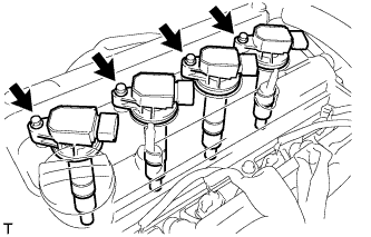
| 11. INSTALL NO. 1 IGNITION COIL |
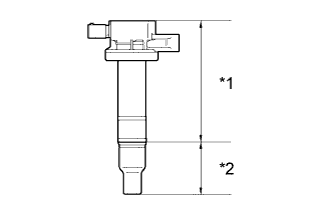
Install the 4 ignition coils with the 4 bolts.
- Torque:
- 9.0 N*m{92 kgf*cm, 80 in.*lbf}
- NOTICE:
- If the body or cap of the ignition coil is dropped or subjected to a strong impact, replace the ignition coil with a new one.
Text in Illustration*1
| Body
|
*2
| Cap
|
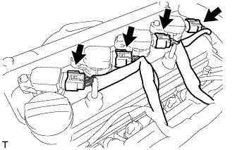
Connect the 4 ignition coil connectors.
| 12. INSTALL WATER FILLER SUB-ASSEMBLY |
Connect the No. 1 radiator hose to the cylinder head.
Install the water filler sub-assembly with 2 nuts.
- Torque:
- 7.5 N*m{76 kgf*cm, 66 in.*lbf}
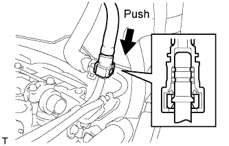
| 13. INSTALL FUEL TUBE SUB-ASSEMBLY |
Insert the fuel tube connector into the fuel delivery pipe until a click sound can be heard.
- NOTICE:
- Check that there are no scratches or foreign matter around the disconnected parts of the fuel tube connector and pipe before performing this work.
- After connecting the fuel tube, check that the fuel tube connector and pipe are securely connected by pulling them.
Install the fuel pipe clamp.
| 14. INSTALL VENTILATION HOSE |
Install the ventilation hose.