Air Conditioning System (For Manual Air Conditioning System) Blower Motor Circuit
DESCRIPTION
WIRING DIAGRAM
INSPECTION PROCEDURE
INSPECT RELAY (HTR)
CHECK HARNESS AND CONNECTOR (A/C AMPLIFIER - BATTERY)
INSPECT BLOWER MOTOR
INSPECT BLOWER RESISTOR
INSPECT NO. 2 HEATER CONTROL (BLOWER SWITCH)
CHECK HARNESS AND CONNECTOR (A/C AMPLIFIER - BATTERY)
CHECK HARNESS AND CONNECTOR (NO. 2 HEATER CONTROL (BLOWER SWITCH) - BATTERY)
CHECK HARNESS AND CONNECTOR (BLOWER RESISTOR - NO. 2 HEATER CONTROL (BLOWER SWITCH))
CHECK HARNESS AND CONNECTOR (BLOWER MOTOR - BLOWER RESISTOR, NO. 2 HEATER CONTROL)
CHECK HARNESS AND CONNECTOR (BLOWER MOTOR - BATTERY, BODY GROUND)
AIR CONDITIONING SYSTEM (for Manual Air Conditioning System) - Blower Motor Circuit |
DESCRIPTION
When the No. 2 heater control (blower switch) is operated, the HTR relay will turn on and send current to operate the blower motor. Operating the No. 2 heater control (blower switch) adjusts the flow of current between the blower resistor and body ground, thus, adjusting the speed of the blower motor.
WIRING DIAGRAM
INSPECTION PROCEDURE
- NOTICE:
- Inspect the fuses for circuits related to this system before performing the following inspection procedure.
Remove the HTR relay from the instrument panel junction block.
Measure the resistance according to the value(s) in the table below.
- Standard Resistance:
Tester Connection
| Specified Condition
|
3 - 4
| Below 1 Ω
|
3 - 4
| 10 kΩ or higher (When battery voltage is applied to terminals 1 and 2)
|
3 - 5
| 10 kΩ or higher
|
3 - 5
| Below 1 Ω (When battery voltage is applied to terminals 1 and 2)
|
| 2.CHECK HARNESS AND CONNECTOR (A/C AMPLIFIER - BATTERY) |
Disconnect the connector from the A/C amplifier.
Measure the voltage according to the value(s) in the table below.
- Standard Voltage:
Tester Connection
| Condition
| Specified Condition
|
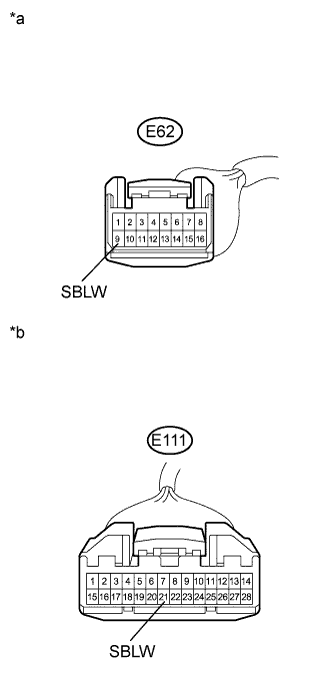
E62-9 (SBLW) - Body ground*1
| Ignition switch ON
Blower switch: OFF
| 11 to 14 V
|
E62-9 (SBLW) - Body ground*1
| Ignition switch ON
Blower switch: ON
| Below 1 V
|
E111-21 (SBLW) - Body ground*2
| Ignition switch ON
Blower switch: OFF
| 11 to 14 V
|
E111-21 (SBLW) - Body ground*2
| Ignition switch ON
Blower switch: ON
| Below 1 V
|
- *1: except TMC Made 2AZ-FE
- *2: for TMC Made and except TMC Made 2ZR-FE
Text in Illustration*a
| Front view of wire harness connector
(to A/C Amplifier (except TMC Made 2AZ-FE))
|
*b
| Front view of wire harness connector
(to A/C Amplifier (for TMC Made and except TMC Made 2ZR-FE))
|
Remove the blower motor.
Disconnect the connector from the blower motor.
Connect a positive (+) lead from the battery to terminal 2 and a negative (-) lead from the battery to terminal 1, and check that the motor operates.
- OK:
- The blower motor operates smoothly.
Text in Illustration*a
| Component without harness connected
(Blower Motor)
|
| 4.INSPECT BLOWER RESISTOR |
Remove the blower resistor.
Disconnect the connector from the blower resistor.
Measure the resistance according to the value(s) in the table below.
- Standard Resistance:
Tester Connection
| Condition
| Specified Condition
|
E66-1 (HI) - E66-4 (E)
| Always
| 3.12 to 3.60 Ω
|
E66-1 (HI) - E66-2 (M1)
| Always
| 1.45 to 1.67 Ω
|
E66-1 (HI) - E66-3 (M2)
| Always
| 0.52 to 0.60 Ω
|
Text in Illustration*a
| Component without harness connected
(Blower Resister)
|
| 5.INSPECT NO. 2 HEATER CONTROL (BLOWER SWITCH) |
Remove the No. 2 heater control (blower switch).
Disconnect the connector from the No. 2 heater control (blower switch).
Measure the resistance according to the value(s) in the table below.
- Standard Resistance:
Tester Connection
| Switch Condition
| Specified Condition
|
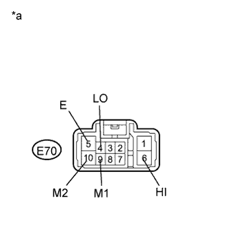
E70-4 (LO), E70-6 (HI), E70-9 (M1), E70-10 (M2) - E70-5 (E)
| Blower switch: OFF
| 10 kΩ or higher
|
E70-4 (LO) - E70-5 (E)
| Blower switch: LO
| Below 1 Ω
|
E70-4 (LO), E70-9 (M1) - E70-5 (E)
| Blower switch: M1
| Below 1 Ω
|
E70-4 (LO), E70-10 (M2) - E70-5 (E)
| Blower switch: M2
| Below 1 Ω
|
E70-4 (LO), E70-6 (HI) - E70-5 (E)
| Blower switch: HI
| Below 1 Ω
|
Text in Illustration*a
| Component without harness connected
(No. 2 Heater Control (Blower Switch))
|
| 6.CHECK HARNESS AND CONNECTOR (A/C AMPLIFIER - BATTERY) |
Measure the voltage according to the value(s) in the table below.
- Standard Voltage:
Tester Connection
| Switch Condition
| Specified Condition
|
E62-9 (SBLW) - Body ground*1
| Ignition switch ON
| 11 to 14 V
|
E62-9 (SBLW) - Body ground*1
| Ignition switch off
| Below 1 V
|
E111-21 (SBLW) - Body ground*2
| Ignition switch ON
| 11 to 14 V
|
E111-21 (SBLW) - Body ground*2
| Ignition switch off
| Below 1 V
|
- *1: except TMC Made 2AZ-FE
- *2: for TMC Made and except TMC Made 2ZR-FE
Text in Illustration*a
| Front view of wire harness connector
(to A/C Amplifier (except TMC Made 2AZ-FE))
|
*b
| Front view of wire harness connector
(to A/C Amplifier (for TMC Made and except TMC Made 2ZR-FE))
|
| | REPAIR OR REPLACE HARNESS OR CONNECTOR |
|
|
| 7.CHECK HARNESS AND CONNECTOR (NO. 2 HEATER CONTROL (BLOWER SWITCH) - BATTERY) |
Measure the voltage according to the value(s) in the table below.
- Standard Voltage:
Tester Connection
| Switch Condition
| Specified Condition
|
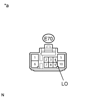
E70-4 (LO) - Body ground
| Ignition switch ON
| 11 to 14 V
|
E70-4 (LO) - Body ground
| Ignition switch off
| Below 1 V
|
Text in Illustration*a
| Front view of wire harness connector
(to No. 2 Heater Control (Blower Switch))
|
| | REPAIR OR REPLACE HARNESS OR CONNECTOR |
|
|
| 8.CHECK HARNESS AND CONNECTOR (BLOWER RESISTOR - NO. 2 HEATER CONTROL (BLOWER SWITCH)) |
Measure the resistance according to the value(s) in the table below.
- Standard Resistance:
Tester Connection
| Condition
| Specified Condition
|
E66-1 (HI) - E70-6 (HI)
| Always
| Below 1 Ω
|
E66-3 (M2) - E70-10 (M2)
| Always
| Below 1 Ω
|
E66-2 (M1) - E70-9 (M1)
| Always
| Below 1 Ω
|
E66-4 (E) - Body ground
| Always
| Below 1 Ω
|
E70-5 (E) - Body ground
| Always
| Below 1 Ω
|
E66-1 (HI) - Body ground
| Always
| 10 kΩ or higher
|
E66-3 (M2) - Body ground
| Always
| 10 kΩ or higher
|
E66-2 (M1) - Body ground
| Always
| 10 kΩ or higher
|
| | REPAIR OR REPLACE HARNESS OR CONNECTOR |
|
|
| 9.CHECK HARNESS AND CONNECTOR (BLOWER MOTOR - BLOWER RESISTOR, NO. 2 HEATER CONTROL) |
Measure the resistance according to the value(s) in the table below.
- Standard Resistance:
Tester Connection
| Condition
| Specified Condition
|
E64-1 - E66-1 (HI)
| Always
| Below 1 Ω
|
E64-1 - E70-6 (HI)
| Always
| Below 1 Ω
|
E64-1 - Body ground
| Always
| 10 kΩ or higher
|
| | REPAIR OR REPLACE HARNESS OR CONNECTOR |
|
|
| 10.CHECK HARNESS AND CONNECTOR (BLOWER MOTOR - BATTERY, BODY GROUND) |
Reconnect the connector to the A/C amplifier.
Reconnect the connector to the blower resistor.
Reconnect the connector to the No. 2 heater control (blower switch).
Measure the voltage according to the value(s) in the table below.
- Standard Voltage:
Tester Connection
| Switch Condition
| Specified Condition
|
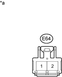
E64-2 - Body ground
| Ignition switch ON
Blower switch: OFF
| Below 1 V
|
E64-2 - Body ground
| Ignition switch ON
Blower switch: ON
| 11 to 14 V
|
Measure the resistance according to the value(s) in the table below.
- Standard Resistance:
Tester Connection
| Switch Condition
| Specified Condition
|
E64-2 - Body ground
| Ignition switch off
Blower switch: OFF
| Below 1 Ω
|
Text in Illustration*a
| Front view of wire harness connector
(to Blower Motor)
|
| | REPAIR OR REPLACE HARNESS OR CONNECTOR |
|
|