Air Conditioning System (For Manual Air Conditioning System) -- System Description |
| GENERAL |
| Control | Outline |
| Variable Capacity Compressor Control | Controls the compressor to turn ON or OFF and the discharge capacity based on the signals from various sensors. |
| Self-diagnosis | Checks the sensors in accordance with operation of air conditioning switches, then clock displays a DTC (Diagnosis Trouble Code) to indicate if there is a malfunction or not (sensor check function). |
| MODE POSITION AND DAMPER OPERATION |
Mode Position and Damper Operation

*1: w/ PTC Heater AssemblyFunctions of Main Dampers Control Damper Operation Position Damper Position Operation Air Inlet Control Damper FRESH A Brings in fresh air. RECIRC B Recirculates internal air. Air Mix Control Damper MAX COLD to MAX HOT Temperature Setting
16°C (61°F) to 30°C (86°F)C - D - E Varies the mixture ratio of the fresh air and the recirculation air in order to regulate the temperature continuously from HOT to COLD. Mode Control Damper DEF 
H, K Defrosts the windshield through the front defroster and side register. FOOT/DEF 
H, J Defrosts the windshield through the front defroster and side register, while air is also blown out from the front footwell register duct and rear foot well register duct*2. FOOT 
H, I Air blows out of the footwell register duct, rear footwell register duct*2, and side register. In addition, air blows out slightly from the front defroster. BI-LEVEL 
F, I Air blows out of the center register, side register, front footwell register duct and rear footwell register duct*2. FACE 
F, K Air blows out of the center register and side register.
*2: for Cold Area
| AIR OUTLETS AND AIRFLOW VOLUME |
Air Outlets and Airflow Volume

The size of the circle ○ indicates the proportion of airflow volume.INDICATION
(MODE)CTR SIDE FOOTWELL DEFROSTER A B C D
FACE

BI-LEVEL

FOOT
FOOT/DEF
DEF
| COMPRESSOR ASSEMBLY WITH PULLEY |
General
The compressor assembly with pulley is a continuously variable capacity type in which its capacity varies with the cooling load of the air conditioning system.
The compressor consists of the shaft, lug plate, piston, shoe, crank chamber, cylinder, and solenoid control valve.
The solenoid control valve adjusts the suction pressure is provided to enable to be controlled as desired.
A plastic DL (Damper Limiter) type A/C pulley is used.
A rotary valve uses suction to pull refrigerant gas into the cylinder.

Operation
The crank chamber is connected to the suction passage. A solenoid control valve is provided between the suction passage (low pressure) and the discharge passage (high pressure).
The solenoid control valve duty cycle is controlled in accordance with the signals from the air conditioning amplifier.

When the solenoid control valve closes (solenoid coil is energized), a difference in pressure is created and the crank chamber pressure decreases. Then, the pressure that is applied to the right side of the piston becomes greater than the pressure that is applied to the left side. This compresses the spring and tilts the lug plate. As a result, there is a large piston stroke and the discharge capacity increases.

When the solenoid control valve opens (solenoid coil is not energized), the pressure is equalized. The pressure applied to the left side of the piston becomes equal to the right side. This is performed when the spring elongates and eliminates the tilt of the lug plate. As a result, there is a small piston stroke and the discharge capacity decreases.

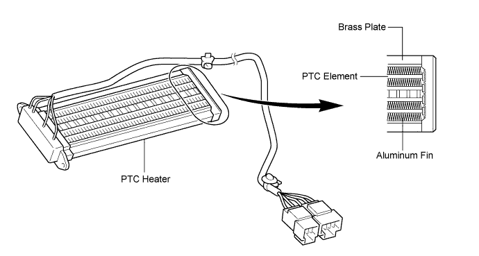
| PTC HEATER (w/ PTC Heater Assembly) |
General
The PTC heater is located above the heater core in the air conditioner unit.
The PTC heater consists of a PTC element, aluminum fin, and brass plate. When current is applied to the PTC element, it generates heat to warm the air that passes through the unit.
PTC Heater Operating Conditions
The PTC heater is turned on and off by the air conditioning amplifier in accordance with the coolant temperature, ambient temperature, engine speed, air mix setting, and electrical load (generator power ratio).
For example, the number of the operating PTC heaters varies by the coolant temperature as in the graph below.
| AMBIENT TEMPERATURE SENSOR |
| EVAPORATOR TEMPERATURE SENSOR |
| A/C PRESSURE SENSOR |
| A/C FLOW SENSOR (for 2ZR-FE) |