Dtc B1411/11 Room Temperature Sensor Circuit
DESCRIPTION
WIRING DIAGRAM
INSPECTION PROCEDURE
READ VALUE USING TECHSTREAM
INSPECT ROOM TEMPERATURE SENSOR
CHECK HARNESS AND CONNECTOR (ROOM TEMPERATURE SENSOR - AIR CONDITIONING AMPLIFIER)
DTC B1411/11 Room Temperature Sensor Circuit |
DESCRIPTION
This sensor detects the cabin temperature that is used as the basis for temperature control and sends a signal to the A/C amplifier.DTC No.
| DTC Detection Condition
| Trouble Area
|
B1411/11
| Open or short in room temperature sensor circuit
| - Room temperature sensor
- Harness or connector between room temperature sensor and A/C amplifier
- A/C amplifier
|
WIRING DIAGRAM
INSPECTION PROCEDURE
| 1.READ VALUE USING TECHSTREAM |
Connect the Techstream to the DLC3.
Turn the ignition switch to ON.
Turn the Techstream on.
Enter the following menus: Body Electrical / Air Conditioner / Data List.
Check the value(s) by referring to the table below.
Air ConditionerTester Display
| Measurement Item/Range
| Normal Condition
| Diagnostic Note
|
Room Temperature Sensor
(Room Temp)
| Room temperature sensor / Min.: -6.5°C (20.3°F), Max.: 57.25°C (135.05°F)
| Actual cabin temperature displayed
| -
|
- OK:
- The display is as specified in the "Normal Condition" column.
- Result:
Result
| Proceed to
|
NG
| A
|
OK (When troubleshooting according to Problem Symptoms Table)
| B
|
OK (When troubleshooting according to DTC)
| C
|
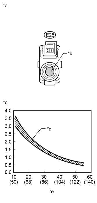
| 2.INSPECT ROOM TEMPERATURE SENSOR |
Remove the room temperature sensor.
Disconnect the connector from the room temperature sensor.
Measure the resistance according to the value(s) in the table below.
- Standard Resistance:
Tester Connection
| Condition
| Specified Condition
|
E25-1 - E25-2
| 10°C (50°F)
| 3.00 to 3.73 kΩ
|
E25-1 - E25-2
| 15°C (59°F)
| 2.45 to 2.88 kΩ
|
E25-1 - E25-2
| 20°C (68°F)
| 1.95 to 2.30 kΩ
|
E25-1 - E25-2
| 25°C (77°F)
| 1.60 to 1.80 kΩ
|
E25-1 - E25-2
| 30°C (86°F)
| 1.28 to 1.47 kΩ
|
E25-1 - E25-2
| 35°C (95°F)
| 1.00 to 1.22 kΩ
|
E25-1 - E25-2
| 40°C (104°F)
| 0.80 to 1.00 kΩ
|
E25-1 - E25-2
| 45°C (113°F)
| 0.65 to 0.85 kΩ
|
E25-1 - E25-2
| 50°C (122°F)
| 0.50 to 0.70 kΩ
|
E25-1 - E25-2
| 55°C (131°F)
| 0.44 to 0.60 kΩ
|
E25-1 - E25-2
| 60°C (140°F)
| 0.36 to 0.50 kΩ
|
- NOTICE:
- Hold the sensor only by its connector. Touching the sensor may change the resistance value.
- When measuring, the sensor temperature must be the same as the ambient temperature.
- HINT:
- As the temperature increases, the resistance decreases (see the graph).
Text in Illustration*a
| Component without harness connected
(Room Temperature Sensor)
|
*b
| Sensing Portion
|
*c
| Resistance (kΩ)
|
*d
| Allowable Range
|
*e
| Temperature (°C (°F))
|
| 3.CHECK HARNESS AND CONNECTOR (ROOM TEMPERATURE SENSOR - AIR CONDITIONING AMPLIFIER) |
Disconnect the connector from the A/C amplifier.
Measure the resistance according to the value(s) in the table below.
- Standard Resistance:
Tester Connection
| Condition
| Specified Condition
|
E30-29 (TR) - E25-1
| Always
| Below 1 Ω
|
E30-34 (SG-1) - E25-2
| Always
| Below 1 Ω
|
E30-29 (TR) - Body ground
| Always
| 10 kΩ or higher
|
E30-34 (SG-1) - Body ground
| Always
| 10 kΩ or higher
|
| | REPAIR OR REPLACE HARNESS OR CONNECTOR |
|
|