Air Conditioning System (For Automatic Air Conditioning System) -- System Description |
| GENERAL |
| Control | Outline |
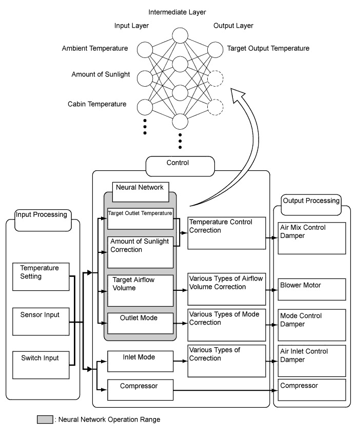
| Neural Network Control | This control is capable of effecting complex control by artificially simulating the information processing method of the nervous system of living organisms in order to establish a complex input or output relationship that is similar to a human brain. |
| Outlet Air Temperature Control | In compliance with the temperature set at the temperature control switch, the neural network control calculates the outlet temperature based on the input signals from various sensors. In addition, corrections in accordance with the signals from the evaporative temperature sensor and engine coolant temperature sensor are added to control the outlet air temperature. |
| Blower Control | Controls the blower motor in accordance with the airflow volume that has been calculated by the neural network control based on the input signals from various sensors. |
| Air Outlet Control | Automatically switches the outlets in accordance with the outlet mode ratio that has been calculated by the neural network control based on the input signals from various sensors. |
| Air Inlet Control | Automatically controls the air inlet control damper in accordance with the airflow volume that has been calculated by the neural network control. |
| Variable Capacity Compressor Control | Controls the compressor to turn ON or OFF and the discharge capacity based on the signals from various sensors. |
| Ambient Temperature Indication Control | Based on the signals from the ambient temperature sensor, this control calculates the ambient temperature, which is then corrected in the air conditioning amplifier, and shown in the multi-information display in the combination meter. |
| Rear Window Defogger Control | Switches the rear defogger and outside rear view mirror heaters on for 15 minutes when the rear defogger button is pressed. Switches them OFF if the button is pressed while they are operating. |
| Self-diagnosis | Checks the sensors in accordance with the operation of air conditioning switches, then temperature setting displays a DTC (Diagnosis Trouble Code) to indicate if there is a malfunction or not (sensor check function). |
| Drives the actuators through a predetermined sequence in accordance with the operation of the air conditioning switches (actuator check function). |
| NEURAL NETWORK CONTROL |
- In previous automatic air conditioning systems, the A/C amplifier determined the required outlet air temperature and blower air volume in accordance with the calculation formula that has been obtained based on information received from the sensors.
However, because the senses of a person are rather complex, a given temperature is sensed differently, depending on the environment in which the person is situated. For example, a given amount of solar radiation can feel comfortably warm in a cold climate, or extremely uncomfortable in a hot climate. Therefore, as a technique for effecting a higher level of control, a neural network has been adopted in the automatic air conditioning system. With this technique, the data that has been collected under varying environmental conditions is stored in the A/C amplifier. The A/C amplifier can then effect control to provide enhanced air conditioning comfort. - The neural network control consists of neurons in the input layer, intermediate layer, and output layer. The input layer neurons process the input data of the outside temperature, the amount of sunlight, and the cabin temperature based on the outputs of the switches and sensors, and output them to the intermediate layer neurons. Based on this data, the intermediate layer neurons adjust the strength of the links among the neurons. The sum of these is then calculated by the output layer neurons in the form of the required outlet temperature, solar correction, target airflow volume, and outlet mode control volume. Accordingly, the A/C amplifier controls the servo motors and blower motor in accordance with the control volumes that have been calculated by the neural network control.
| MODE POSITION AND DAMPER OPERATION |
Mode position and damper operation

Functions of Main Dampers: Control Damper Operation Position Damper Position Operation Air Inlet Control Damper FRESH A Brings in fresh air. RECIRC B Recirculates internal air. Air Mix Control Damper MAX COLD to MAX HOT Temperature Setting
16°C (61°F) to 30°C (86°F)C - D - E Varies the mixture ratio of the fresh air and the recirculation air in order to regulate the temperature continuously from HOT to COLD. Mode Control Damper DEF 
H, K Defrosts the windshield through the front defroster and side register. FOOT/DEF 
H, J Defrosts the windshield through the front defroster and side register, while air is also blown out from the front foot well register ducts. FOOT 
H, I Air blows out of the footwell register duct and side register. In addition, air blows out slightly from the front defroster. BI-LEVEL 
F, I Air blows out of the center register, side register, and front footwell register ducts. FACE 
F, K Air blows out of the center register and side register.
| AIR OUTLETS AND AIRFLOW VOLUME |
Air Outlets and Airflow Volume

The size of the circle ○ indicates the proportion of airflow volume.INDICATION
(MODE)CTR SIDE FOOTWELL DEFROSTER A B C D
FACE

BI-LEVEL

FOOT
FOOT/DEF
DEF
| BLOWER MOTOR |
| BUS CONNECTOR |
A BUS connector is used in the wire harness connection that connects the servo motor from the A/C amplifier.
for TMC Made

except TMC Made
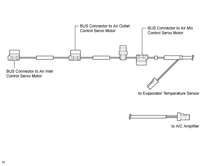
Each BUS connector has a built-in communication/driver IC which communicates with each servo motor connector, actuates the servo motor, and has a position detection function. This enables bus communication for the servo motor wire harness, for a more lightweight construction and a reduced number of wires.

| SERVO MOTOR |
In contrast to the previous type that detects the position using potentiometer voltage, the pulse pattern type servo motor detects the relative position using the 2-bit ON/OFF signals.
The forward and reverse revolutions of this motor are detected by way of two phases, A and B, which output four types of patterns. The air conditioning amplifier counts the number of pulse patterns in order to determine the stopped position.
| COMPRESSOR ASSEMBLY WITH PULLEY |
General
The compressor assembly with pulley is a continuously variable capacity type in which its capacity varies in accordance with the cooling load of the air conditioning system.
The compressor consists of the shaft, lug plate, piston, shoe, crank chamber, cylinder, and solenoid control valve.
The solenoid control valve is provided to enable the suction pressure to be controlled as desired.
A plastic DL (Damper Limiter) type A/C pulley is used.
A rotary type valve is used to suction refrigerant gas into the cylinder.

Operation
The crank chamber is connected to the suction passage. A solenoid control valve is provided between the suction passage (low pressure) and the discharge passage (high pressure).
The solenoid control valve operates under duty cycle control in accordance with the signals from the air conditioning amplifier.

When the solenoid control valve closes (solenoid coil is energized), a difference in pressure is created and the pressure in the crank chamber decreases. Then, the pressure that is applied to the right side of the piston becomes greater than the pressure that is applied to the left side of the piston. This compresses the spring and tilts the lug plate. As a result, there is a large piston stroke and the discharge capacity increases.

When the solenoid control valve opens (solenoid coil is not energized), the difference in pressure disappears. Then, the pressure that is applied to the left side of the piston becomes the same as the pressure that is applied to the right side of the piston. Thus, the spring elongates and eliminates the tilt of the lug plate. As a result, there is a small piston stroke and the discharge capacity decreases.

| ROOM TEMPERATURE SENSOR |
| AMBIENT TEMPERATURE SENSOR |
| EVAPORATOR TEMPERATURE SENSOR |
| SOLAR SENSOR |
| A/C PRESSURE SENSOR |
| PTC HEATER (w/ PTC Heater Assembly) |
General
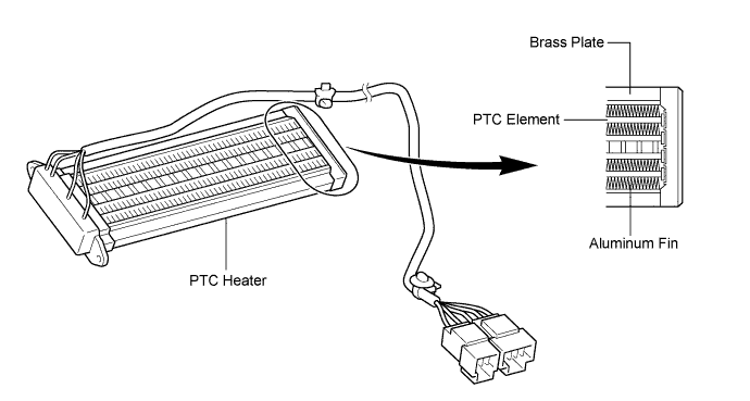
The PTC heater is located above the heater core in the air conditioner unit.
The PTC heater consists of a PTC element, aluminum fin, and brass plate. When current is applied to the PTC element, it generates heat to warm the air that passes through the unit.
PTC Heater Operating Conditions
The PTC heater is turned on and off by the air conditioning amplifier in accordance with the coolant temperature, ambient temperature, engine speed, air mix setting, and electrical load (generator power ratio).
For example, the number of the operating PTC heaters varies by the coolant temperature as in the graph below.
| A/C FLOW SENSOR (for 2ZR-FE) |