Engine Hood Courtesy Switch -- Installation |
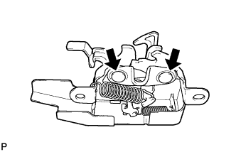
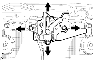
| 1. INSTALL HOOD LOCK ASSEMBLY |
Apply MP grease to the sliding areas of the lock.
 |
Connect the hood lock control cable.
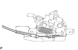 |
Install the hood lock assembly with the 3 bolts.
- Torque:
- Centering Bolt:
- 7.5 N*m{77 kgf*cm, 66 in.*lbf}
- Standard Bolt:
- 8.0 N*m{82 kgf*cm, 71 in.*lbf}
 |
| 2. INSPECT HOOD SUB-ASSEMBLY |
Check that the clearance measurements of areas A through E are within each standard range.

- Standard Clearance:
Area Measurement Area Measurement A 3.1 to 6.1 mm (0.122 to 0.240 in.) D 4.8 mm (0.189 in.) B -1.5 to 1.5 mm (-0.0591 to 0.0591 in.) E 0.7 mm (0.0276 in.) C 2.3 to 5.3 mm (0.0906 to 0.209 in.) - -
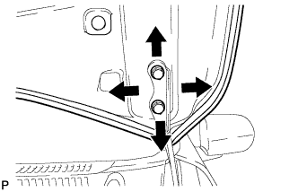
| 3. ADJUST HOOD SUB-ASSEMBLY |
Horizontally and vertically adjust the hood.
Loosen the 4 hinge bolts of the hood.
Adjust the clearance between the hood and front fender by moving the hood.
Tighten the 4 hinge bolts after the adjustment.
- Torque:
- 13 N*m{133 kgf*cm, 10 ft.*lbf}
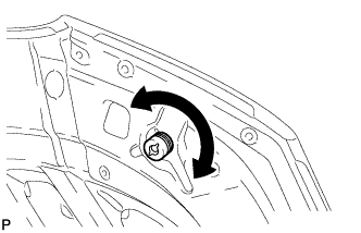
Adjust the height of the front end of the hood using the cushion rubber.
Adjust the cushion rubber so that the heights of the hood and fender are aligned.
- HINT:
- Raise or lower the front end of the hood by turning the cushion rubber.
Adjust the hood lock.
Loosen the 3 bolts.
Tighten the bolts after the adjustment.
- Torque:
- 8.0 N*m{82 kgf*cm, 71 in.*lbf}
Check that the striker engages the hood lock smoothly.
| 4. INSTALL FRONT BUMPER ASSEMBLY (for 2AZ-FE) |
Connect the 2 fog light connectors.
Engage the 6 claws and install the front bumper assembly as shown in the illustration.
 |
Install the 2 screws, 7 clips and 2 bolts.
- Torque:
- Bolt:
- 5.0 N*m{51 kgf*cm, 44 in.*lbf}
Install the pin hold clip.
Text in Illustration *a Correct *b Incorrect - NOTICE:
- Insert the pin hold clip with the slot aligned vertically. Do not rotate the clip after inserting it. After installation, confirm that the slot is vertical.
- HINT:
- Use the same procedure for the RH side and LH side.
 |
| 5. INSTALL FRONT BUMPER ASSEMBLY (for 2ZR-FE) |
w/ Fog Light:
Connect the 2 fog light connectors.
Engage the 6 claws and install the front bumper assembly as shown in the illustration.
|
Install the 4 screws, 7 clips and 2 bolts.
- Torque:
- Bolt:
- 5.0 N*m{51 kgf*cm, 44 in.*lbf}
Install the pin hold clip.
Text in Illustration *a Correct *b Incorrect - NOTICE:
- Insert the pin hold clip with the slot aligned vertically. Do not rotate the clip after inserting it. After installation, confirm that the slot is vertical.
- HINT:
- Use the same procedure for the RH side and LH side.
|
| 6. INSTALL NO. 4 ENGINE UNDER COVER (for 2AZ-FE) |
Install the No. 4 engine under cover with the 4 screws and 4 clips.
| 7. INSTALL RADIATOR GRILLE PROTECTOR |
Install the 2 radiator grille protectors.
- Torque:
- 5.0 N*m{51 kgf*cm, 44 in.*lbf}
| 8. ADJUST FOG LIGHT AIMING (w/ Fog Light) |