Theft Deterrent System Theft Warning Ecu Power Source Circuit
DESCRIPTION
WIRING DIAGRAM
INSPECTION PROCEDURE
CHECK THEFT WARNING ECU ASSEMBLY
CHECK HARNESS AND CONNECTOR (THEFT WARNING ECU ASSEMBLY - BODY GROUND)
CHECK HARNESS AND CONNECTOR (BATTERY - INSTRUMENT PANEL JUNCTION BLOCK)
CHECK INSTRUMENT PANEL JUNCTION BLOCK (POWER SOURCE)
CHECK HARNESS AND CONNECTOR (INSTRUMENT PANEL JUNCTION BLOCK - THEFT WARNING ECU ASSEMBLY)
THEFT DETERRENT SYSTEM - Theft Warning ECU Power Source Circuit |
DESCRIPTION
This circuit provides power for theft warning ECU assembly operation.
WIRING DIAGRAM
INSPECTION PROCEDURE
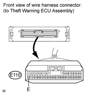
| 1.CHECK THEFT WARNING ECU ASSEMBLY |
Measure the voltage according to the value(s) in the table below.
- Standard Voltage:
Tester Connection
| Condition
| Specified Condition
|
E110-11 (+B1) - Body ground
| Always
| 11 to 14 V
|
| 2.CHECK HARNESS AND CONNECTOR (THEFT WARNING ECU ASSEMBLY - BODY GROUND) |
Disconnect the E110 theft warning ECU assembly connector.
Measure the resistance according to the value(s) in the table below.
- Standard Resistance:
Tester Connection
| Condition
| Specified Condition
|
E110-16 (E) - Body ground
| Always
| Below 1 Ω
|
| | REPAIR OR REPLACE HARNESS OR CONNECTOR |
|
|
| 3.CHECK HARNESS AND CONNECTOR (BATTERY - INSTRUMENT PANEL JUNCTION BLOCK) |
Disconnect the 2B instrument panel junction block connector.
Measure the voltage according to the value(s) in the table below.
- Standard Voltage:
Tester Connection
| Condition
| Specified Condition
|
2B-30 - Body ground
| Always
| 11 to 14 V
|
| | REPAIR OR REPLACE HARNESS OR CONNECTOR OR SHORT PIN OR ECU-B |
|
|
| 4.CHECK INSTRUMENT PANEL JUNCTION BLOCK (POWER SOURCE) |
Reconnect the 2B instrument panel junction block connector.
Measure the voltage according to the value(s) in the table below.
- Standard Voltage:
Tester Connection
| Condition
| Specified Condition
|
2H-12 - Body ground
| Always
| 11 to 14 V
|
| | REPLACE MAIN BODY ECU (INSTRUMENT PANEL JUNCTION BLOCK) |
|
|
| 5.CHECK HARNESS AND CONNECTOR (INSTRUMENT PANEL JUNCTION BLOCK - THEFT WARNING ECU ASSEMBLY) |
Disconnect the 2H instrument panel junction block and E110 theft warning ECU assembly connectors.
Measure the resistance according to the value(s) in the table below.
- Standard Resistance:
Tester Connection
| Condition
| Specified Condition
|
2H-12 - E110-11 (+B1)
| Always
| Below 1 Ω
|
2H-12 - Body ground
| Always
| 10 kΩ or higher
|
| | REPAIR OR REPLACE HARNESS OR CONNECTOR |
|
|