Lin Communication System -- Terminals Of Ecu |
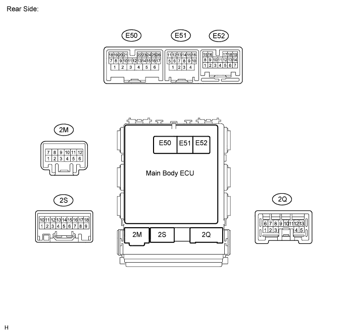
| CHECK MAIN BODY ECU (INSTRUMENT PANEL JUNCTION BLOCK) |
Disconnect the 2B, 2E, 2F and 2G junction block and E51 ECU connectors.

Measure the voltage and resistance according to the value(s) in the table below.
Tester Connection Wiring Color Terminal Description Condition Specified Condition 2B-30 (BECU)* - Body ground W - Body ground Battery power supply Always 11 to 14 V 2F-5 (ACC) - Body ground L - Body ground ACC power supply Engine switch on (ACC) 11 to 14 V 2G-1 (IG) - Body ground W - Body ground Battery power supply Engine switch on (IG) 11 to 14 V 2E-17 (GND1) - Body ground W-B - Body ground Ground Always Below 1 Ω E51-4 (GND2) - Body ground W-B - Body ground Ground Always Below 1 Ω - *: w/o Smart Key System
- *: w/o Smart Key System
Reconnect the 2B, 2E, 2F and 2G junction block and E51 ECU connectors.
Measure the pulse according to the value(s) in the table below.
If the result is not as specified, the ECU may have a malfunction.Tester Connection Wiring Color Terminal Description Condition Specified Condition 2C-12 (LIN1) - E51-4 (GND2) V - W-B LIN Communication line Engine switch on (IG) Pulse generation
| CHECK CERTIFICATION ECU (SMART KEY ECU ASSEMBLY) |

Disconnect the E36 ECU connector.
Measure the voltage and resistance according to the value(s) in the table below.
If the result is not as specified, there may be a malfunction on the wire harness side.Tester Connection Wiring Color Terminal Description Condition Specified Condition E36-1 (+B) - E36-17 (E) GR - W-B Battery power supply Always 11 to 14 V E36-17 (E) - Body ground W-B - Body ground Ground Always Below 1 Ω Reconnect the E36 ECU connector.
Measure the voltage and pulse according to value(s) in the table below.
If the result is not as specified, the ECU may have a malfunction.Tester Connection Wiring Color Terminal Description Condition Specified Condition E36-18 (IG) - E36-17 (E) B - W-B Engine switch power supply Engine switch on (IG) 11 to 14 V E36-18 (IG) - E36-17 (E) B - W-B Engine switch power supply Engine switch off Below 1 V E36-10 (LIN) - E36-17 (E) V - W-B LIN Communication line Engine switch on (IG) Pulse generation
| CHECK ID CODE BOX (IMMOBILISER CODE ECU) |

Disconnect the E22 ECU connector.
Measure the voltage and resistance according to the value(s) in the table below.
If the result is not as specified, there may be a malfunction on the wire harness side.Tester Connection Wiring Color Terminal Description Condition Specified Condition E22-1 (+B) - E22-8 (GND) GR - W-B Battery power supply Always 11 to 14 V E22-8 (GND) - Body ground W-B - Body ground Ground Always Below 1 Ω Reconnect the E22 ECU connector.
Measure the pulse according to value(s) in the table below.
If the result is not as specified, the ECU may have a malfunction.Tester Connection Wiring Color Terminal Description Condition Specified Condition E22-3 (LIN1) - E22-8 (GND) V - W-B LIN Communication line Engine switch on (IG) Pulse generation
| CHECK STEERING LOCK ECU (STEERING LOCK ACTUATOR ASSEMBLY) |

Disconnect the E39 ECU connector.
Measure the voltage and resistance according to the value(s) in the table below.
If the result is not as specified, there may be a malfunction on the wire harness side.Tester Connection Wiring Color Terminal Description Condition Specified Condition E39-7 (B) - E39-1 (GND) L - W-B Battery power supply Always 11 to 14 V E39-1 (GND) - Body ground W-B - Body ground Ground Always Below 1 Ω E39-6 (IG2) - E39-1 (GND) B - W-B Engine switch power supply Engine switch on (IG) 11 to 14 V E39-6 (IG2) - E39-1 (GND) B - W-B Engine switch power supply Engine switch off Below 1 V Reconnect the E39 ECU connector.
Measure the pulse according to value(s) in the table below.
If the result is not as specified, the ECU may have a malfunction.Tester Connection Wiring Color Terminal Description Condition Specified Condition E39-5 (LIN) - E39-1 (GND) V - W-B LIN Communication line Engine switch on (IG) Pulse generation