Dtc B1579 Voice Recognition Microphone Disconnected
DESCRIPTION
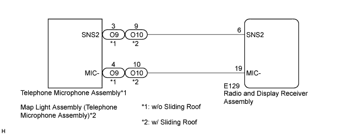
WIRING DIAGRAM
INSPECTION PROCEDURE
INSPECT RADIO AND DISPLAY RECEIVER ASSEMBLY
CHECK HARNESS AND CONNECTOR (RADIO AND DISPLAY RECEIVER ASSEMBLY - TELEPHONE MICROPHONE ASSEMBLY)
CHECK HARNESS AND CONNECTOR (RADIO AND DISPLAY RECEIVER ASSEMBLY - MAP LIGHT ASSEMBLY (TELEPHONE MICROPHONE ASSEMBLY))
INSPECT MAP LIGHT ASSEMBLY (TELEPHONE MICROPHONE ASSEMBLY)
REPLACE TELEPHONE MICROPHONE ASSEMBLY
DTC B1579 Voice Recognition Microphone Disconnected |
DESCRIPTION
The radio and display receiver assembly and telephone microphone assembly are connected to each other using the microphone connection detection signal lines (w/o Sliding Roof).The radio and display receiver assembly and map light assembly (telephone microphone assembly) are connected to each other using the microphone connection detection signal lines (w/ Sliding Roof).This DTC is stored when a microphone connection detection signal line is disconnected.DTC No.
| DTC Detection Condition
| Trouble Area
|
B1579
| Telephone microphone signal is lost.
| - Map light assembly*1
- Telephone microphone assembly
- Radio and display receiver assembly
- Harness or connector
|
- *1: w/ Sliding Roof
WIRING DIAGRAM
INSPECTION PROCEDURE
| 1.INSPECT RADIO AND DISPLAY RECEIVER ASSEMBLY |
Measure the resistance according to the value(s) in the table below.
- Standard Resistance:
Tester Connection
| Condition
| Specified Condition
|
E129-19 (MIC-) - Body ground
| Always
| Below 1 Ω
|
Text in Illustration*a
| Component with harness connected
(Radio and Display Receiver Assembly)
|
Proceed to the next step based on the check result.
- Result:
Result
| Proceed to
|
NG
| A
|
OK (w/o Sliding Roof)
| B
|
OK (w/ Sliding Roof)
| C
|
| 2.CHECK HARNESS AND CONNECTOR (RADIO AND DISPLAY RECEIVER ASSEMBLY - TELEPHONE MICROPHONE ASSEMBLY) |
Disconnect the E129 radio and display receiver assembly connector.
Disconnect the O9 telephone microphone assembly connector.
Measure the resistance according to the value(s) in the table below.
- Standard Resistance:
Tester Connection
| Condition
| Specified Condition
|
E129-6 (SNS2) - O9-3 (SNS2)
| Always
| Below 1 Ω
|
E129-19 (MIC-) - O9-4 (MIC-)
| Always
| Below 1 Ω
|
E129-6 (SNS2) - Body ground
| Always
| 10 kΩ or higher
|
E129-19 (MIC-) - Body ground
| Always
| 10 kΩ or higher
|
| | REPAIR OR REPLACE HARNESS OR CONNECTOR |
|
|
| 3.CHECK HARNESS AND CONNECTOR (RADIO AND DISPLAY RECEIVER ASSEMBLY - MAP LIGHT ASSEMBLY (TELEPHONE MICROPHONE ASSEMBLY)) |
Disconnect the E129 radio and display receiver assembly connector.
Disconnect the O10 map light assembly (telephone microphone assembly) connector.
Measure the resistance according to the value(s) in the table below.
- Standard Resistance:
Tester Connection
| Condition
| Specified Condition
|
E129-6 (SNS2) - O10-9 (SNS2)
| Always
| Below 1 Ω
|
E129-19 (MIC-) - O10-10 (MIC-)
| Always
| Below 1 Ω
|
E129-6 (SNS2) - Body ground
| Always
| 10 kΩ or higher
|
E129-19 (MIC-) - Body ground
| Always
| 10 kΩ or higher
|
| | REPAIR OR REPLACE HARNESS OR CONNECTOR |
|
|
| 4.INSPECT MAP LIGHT ASSEMBLY (TELEPHONE MICROPHONE ASSEMBLY) |
Measure the resistance according to the value(s) in the table below.
- Standard Resistance:
Tester Connection
| Condition
| Specified Condition
|
O10-9 (SNS2) - O10-10 (MIC-)
| Always
| Below 1 Ω
|
Text in Illustration*a
| Component without harness connected
(Map Light Assembly (Telephone Microphone Assembly))
|
| 5.REPLACE TELEPHONE MICROPHONE ASSEMBLY |
Replace the telephone microphone assembly (COROLLA_ZRE142 RM000001Q0103IX.html).
Clear the DTCs (COROLLA_ZRE142 RM0000011BU0KAX.html).
Recheck for DTCs and check that no DTCs are output.
- OK:
- No DTCs are output.