Dtc C1511 Torque Sensor Circuit Malfunction
DESCRIPTION
WIRING DIAGRAM
INSPECTION PROCEDURE
CHECK CONNECTOR CONNECTION CONDITION (TORQUE SENSOR - ECU)
CHECK POWER STEERING ECU (TOQUE SENSOR OUTPUT)
CHECK STEERING COLUMN ASSEMBLY (TORQUE SENSOR)
DTC C1511 Torque Sensor Circuit Malfunction |
DTC C1512 Torque Sensor Circuit Malfunction |
DTC C1513 Torque Sensor Circuit Malfunction |
DTC C1514 Torque Sensor Power Supply Abnormal |
DTC C1517 Torque Hold Abnormal |
DESCRIPTION
The power steering ECU calculates assisting power based on steering torque signals from the torque sensor. If these DTCs are stored in the power steering ECU, the ECU stops steering power assist as a fail-safe function.DTC No.
| DTC Detection Condition
| Trouble Area
|
C1511
| Torque sensor (TRQ1) signal error or stop
| - Steering column assembly (torque sensor)
- Power steering ECU
|
C1512
| Torque sensor (TRQ2) signal error or stop
|
C1513
| Deviation between torque sensor TRQ1 and TRQ2 exceeds specified value
|
C1514
| Torque sensor power source voltage error
|
C1517
| Temporary control due to malfunction related to torque sensor continues for long time
|
WIRING DIAGRAM
INSPECTION PROCEDURE
- NOTICE:
- If the power steering ECU has been replaced with a new one, perform the assist map writing and the torque sensor zero point calibration (COROLLA_ZRE142 RM00000275305DX.html).
- If the steering column assembly has been replaced with a new one, perform the torque sensor zero point calibration after performing the initialization of the torque sensor zero point value (COROLLA_ZRE142 RM00000275305DX.html).
| 1.CHECK CONNECTOR CONNECTION CONDITION (TORQUE SENSOR - ECU) |
Check the installation condition of the torque sensor connector.
- OK:
- Torque sensor connector is securely connected to the power steering ECU.
| 2.CHECK POWER STEERING ECU (TOQUE SENSOR OUTPUT) |
Turn the ignition switch on (IG).
Measure the voltage according to the value(s) in the table below.
- Standard Voltage:
Tester Connection
| Switch Condition
| Specified Condition
|
a3-6 (TRQV) - a3-8 (TRQG)
| Ignition switch on (IG)
| 4.5 to 5.5 V
|
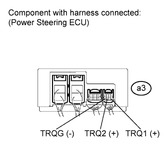
| 3.CHECK STEERING COLUMN ASSEMBLY (TORQUE SENSOR) |
Turn the ignition switch on (IG).
Measure the voltage according to the value(s) in the table below.
- Standard Voltage:
Tester Connection
| Switch Condition (Steering Position)
| Specified Condition
|
a3-5 (TRQ1) - a3-8 (TRQG)
| Ignition switch on (IG)
Center position
| 2.3 to 2.7 V
|
a3-7 (TRQ2) - a3-8 (TRQG)
| Ignition switch on (IG)
Center position
| 2.3 to 2.7 V
|
a3-5 (TRQ1) - a3-8 (TRQG)
| Ignition switch on (IG)
Turned to right
| 2.5 to 3.8 V
|
a3-7 (TRQ2) - a3-8 (TRQG)
| Ignition switch on (IG)
Turned to right
| 1.2 to 2.5 V
|
a3-5 (TRQ1) - a3-8 (TRQG)
| Ignition switch on (IG)
Turned to left
| 1.2 to 2.5 V
|
a3-7 (TRQ2) - a3-8 (TRQG)
| Ignition switch on (IG)
Turned to left
| 2.5 to 3.8 V
|
Under each condition, measure the voltage at terminals TRQ1 and TRQ2, and calculate the sum.
- Standard Voltage:
Inspection Item
| Condition (Steering Wheel Position)
| Specified Condition
|
Sum of voltage between a3-5 (TRQ1) and a3-8 (TRQG) and voltage between a3-7 (TRQ2) and a3-8 (TRQG)
| Ignition switch on (IG)
Steering wheel not being turned (without load)
| Between 4.75 V and 5.25 V
|
Ignition switch on (IG)
Steering wheel being turned to the right with vehicle stopped
|
Ignition switch on (IG)
Steering wheel being turned to the left with vehicle stopped
|