Rear Brake (For Disc Type) Installation
Brake. Corolla. Zre142 Aze141
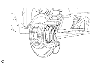
INSTALL REAR DISC
INSTALL REAR DISC BRAKE CYLINDER MOUNTING
INSTALL REAR DISC BRAKE BUSHING DUST BOOT
INSTALL REAR DISC BRAKE PAD GUIDE PIN
INSTALL REAR DISC BRAKE PAD SUPPORT PLATE
INSTALL REAR DISC BRAKE ANTI-SQUEAL SHIM
INSTALL REAR DISC BRAKE PAD
INSTALL REAR DISC BRAKE CYLINDER ASSEMBLY
CONNECT REAR BRAKE FLEXIBLE HOSE
CONNECT NO. 3 PARKING BRAKE CABLE ASSEMBLY
INSTALL PARKING BRAKE LEVER PROTECTOR
FILL RESERVOIR WITH BRAKE FLUID
BLEED BRAKE LINE
INSPECT FOR BRAKE FLUID LEAK
INSPECT FLUID LEVEL
ADJUST PARKING BRAKE LEVER TRAVEL
INSPECT REAR DISC BRAKE CYLINDER OPERATION LEVER AND STOPPER CLEARANCE
INSTALL REAR WHEEL
INSTALL UPPER CONSOLE PANEL SUB-ASSEMBLY
INSTALL CENTER NO. 1 INSTRUMENT CLUSTER FINISH PANEL ASSEMBLY (for Manual Transaxle)
INSTALL CENTER NO. 1 INSTRUMENT CLUSTER FINISH PANEL ASSEMBLY (for Automatic Transaxle)
INSTALL SHIFT LEVER KNOB SUB-ASSEMBLY (for Manual Transaxle)
INSTALL SHIFT LEVER KNOB SUB-ASSEMBLY (for Automatic Transaxle)
INSTALL LOWER INSTRUMENT PANEL FINISH PANEL LH
INSTALL LOWER INSTRUMENT PANEL FINISH PANEL RH
Rear Brake (For Disc Type) -- Installation |
Align the matchmarks of the disc and axle hub and install the disc.
- NOTICE:
- When replacing the disc with a new one, select the installation position where the rear disc has minimal runout.
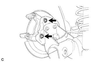
| 2. INSTALL REAR DISC BRAKE CYLINDER MOUNTING |
Install the rear disc brake cylinder mounting to the axle beam with the 2 bolts.
- Torque:
- 63 N*m{642 kgf*cm, 46 ft.*lbf}
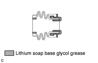
| 3. INSTALL REAR DISC BRAKE BUSHING DUST BOOT |
Apply a light layer of lithium soap base glycol grease to the entire circumference of 2 new rear disc brake bushing dust boots.
- HINT:
- Apply at least 0.3 g (0.01 oz.) of lithium soap base glycol grease to each rear disc brake bushing dust boot.
Install the 2 rear disc brake bushing dust boots to the rear disc brake cylinder mounting.
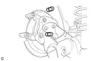
| 4. INSTALL REAR DISC BRAKE PAD GUIDE PIN |
Apply a light layer of lithium soap base glycol grease to the sliding and sealing surfaces of the 2 rear disc brake pad guide pins.
Install the 2 rear disc brake pad guide pins to the rear disc brake cylinder mounting.
| 5. INSTALL REAR DISC BRAKE PAD SUPPORT PLATE |
Install the 2 rear disc brake pad support plates to the rear disc brake cylinder mounting.
- NOTICE:
- Be sure to install each rear disc brake pad support plate in the correct position and direction.
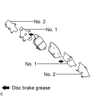
| 6. INSTALL REAR DISC BRAKE ANTI-SQUEAL SHIM |
Apply disc brake grease to the 2 No. 1 anti-squeal shims.
Install the No. 1 anti-squeal shim and No. 2 anti-squeal shim to each brake pad.
- NOTICE:
- When replacing worn pads, the anti-squeal shims must be replaced together with the pads.
- Apply disc brake grease to the area that contacts the anti-squeal shim.
- Disc brake grease may seep out slightly from the areas where the anti-squeal shims are installed.
- Make sure that disc brake grease is not applied onto the lining surface.
| 7. INSTALL REAR DISC BRAKE PAD |
Install the 2 rear disc brake pads to the rear disc brake cylinder mounting.
- NOTICE:
- There should be no oil or grease on the friction surfaces of the disc brake pads or the rear disc.
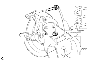
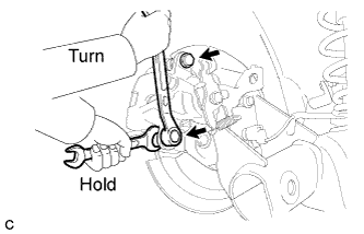
| 8. INSTALL REAR DISC BRAKE CYLINDER ASSEMBLY |
To compensate for pad lining thickness, use SST to adjust the protrusion of the rear disc brake piston by turning it.
- SST
- 09719-12010(09719-01030)
- NOTICE:
- Place the disc between the 2 brake pads and determine the piston return value.
- Turn the rear disc brake piston to the position where the protrusion on the rear disc brake pad lines up properly with the piston groove.
Hold the rear disc brake cylinder slide pin, and install the rear disc brake cylinder assembly to the rear disc brake cylinder mounting with the 2 bolts.
- Torque:
- 35 N*m{357 kgf*cm, 26 ft.*lbf}
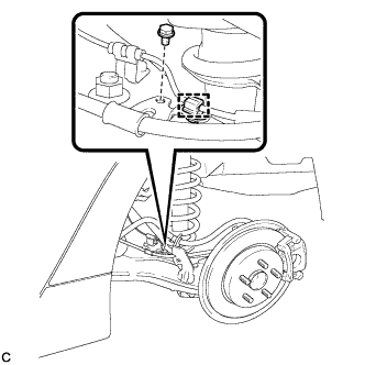
| 9. CONNECT REAR BRAKE FLEXIBLE HOSE |
Connect the flexible hose to the rear disc brake cylinder assembly with the union bolt and a new gasket.
- Torque:
- 29 N*m{296 kgf*cm, 21 ft.*lbf}
- HINT:
- Install the flexible hose lock securely into the lock hole in the disc brake cylinder.
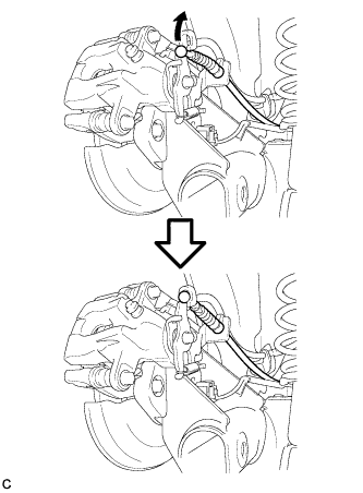
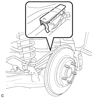
| 10. CONNECT NO. 3 PARKING BRAKE CABLE ASSEMBLY |
Install the No. 3 parking brake cable assembly to the rear disc brake cylinder assembly LH.
- HINT:
- Be sure to engage the No. 3 parking brake cable assembly clip onto the rear disc brake cylinder assembly LH as shown in the illustration.
Connect the No. 3 parking brake cable assembly to the rear disc brake cylinder assembly LH.
Install the bolt.
- Torque:
- 6.0 N*m{61 kgf*cm, 53 in.*lbf}
Engage the clamp to the No. 3 parking brake cable assembly.
| 11. INSTALL PARKING BRAKE LEVER PROTECTOR |
Install the parking brake lever protector to the No. 3 parking brake cable assembly.
| 12. FILL RESERVOIR WITH BRAKE FLUID |
Fill the reservoir with brake fluid.
- Brake Fluid:
- SAE J1703 or FMVSS No. 116 DOT 3
- NOTICE:
- Add brake fluid to keep the level between the MIN and MAX lines of the reservoir while bleeding the brakes.
- NOTICE:
- Bleed the brake line of the wheel farthest from the master cylinder first.
- Add brake fluid to keep the level between the MIN and MAX lines of the reservoir while bleeding the brakes.
Connect a vinyl tube to the bleeder plug.
Depress the brake pedal several times, and then loosen the bleeder plug with the pedal depressed*1.
When fluid stops coming out, tighten the bleeder plug, and then release the brake pedal*2.
Repeat *1 and *2 until all the air in the fluid is completely bled out.
Tighten the bleeder plug completely.
- Torque:
- Front bleeder plug:
- 8.3 N*m{85 kgf*cm, 73 in.*lbf}
- Rear bleeder plug (for Drum Brake):
- 8.5 N*m{87 kgf*cm, 75 in.*lbf}
- Rear bleeder plug (for Disc Brake):
- 10 N*m{102 kgf*cm, 7 ft.*lbf}
Repeat the above procedure for each wheel to bleed the brake line.
| 14. INSPECT FOR BRAKE FLUID LEAK |
Check the fluid level.
If brake fluid level is lower than the MIN line, check for leaks and inspect the disc brake pads. If necessary, refill the reservoir with brake fluid to the MAX line after repair or replacement.
- Brake Fluid:
- SAE J1703 or FMVSS No. 116 DOT 3
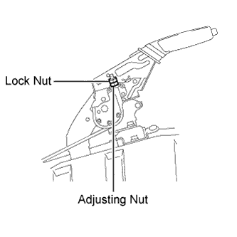
| 16. ADJUST PARKING BRAKE LEVER TRAVEL |
Remove the upper console box assembly (COROLLA_ZRE142 RM000002XV501QX.html).
Completely release the parking brake lever.
Loosen the lock nut and the adjusting nut to completely release the parking brake cable.
Fully depress the brake lever 3 to 5 times with the engine stopped.
Turn the adjusting nut until the parking brake lever travel is corrected to within the specified range.
- Parking brake lever travel:
- 6 to 9 notches at 200 N (20 kgf, 45.0 lbf)
Using a wrench or an equivalent tool, hold the adjusting nut and tighten the lock nut.
- Torque:
- 6.0 N*m{61 kgf*cm, 53 in.*lbf}
Operate the parking brake lever 3 to 4 times, and check the parking brake lever travel.
Check whether the parking brake drags or not.
Install the upper console box assembly (COROLLA_ZRE142 RM000002XV301QX.html).
| 17. INSPECT REAR DISC BRAKE CYLINDER OPERATION LEVER AND STOPPER CLEARANCE |
Release the parking brake lever and check that the clearance measurement between the rear disc brake cylinder operation lever and the stopper is within the specified range.
- Clearance (A):
- 0.5 mm (0.0197 in.) or less
If the clearance is not within the specified range, replace the rear disc brake caliper assembly.
- Torque:
- 103 N*m{1050 kgf*cm, 76 ft.*lbf}
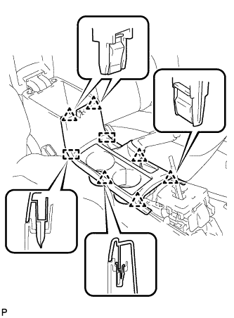
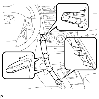
| 19. INSTALL UPPER CONSOLE PANEL SUB-ASSEMBLY |
Engage the 6 clips and 2 guides to install the upper console panel sub-assembly.
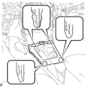
| 20. INSTALL CENTER NO. 1 INSTRUMENT CLUSTER FINISH PANEL ASSEMBLY (for Manual Transaxle) |
Engage the guide.
Engage the 2 claws and 2 clips, and install the center No.1 instrument cluster finish panel assembly.
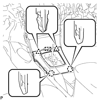
| 21. INSTALL CENTER NO. 1 INSTRUMENT CLUSTER FINISH PANEL ASSEMBLY (for Automatic Transaxle) |
Engage the guide.
Engage the 2 claws and 2 clips, and install the center No.1 instrument cluster finish panel assembly.
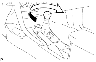
| 22. INSTALL SHIFT LEVER KNOB SUB-ASSEMBLY (for Manual Transaxle) |
Turn the shift lever knob clockwise and install the shift lever knob sub-assembly.
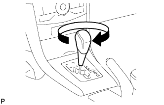
| 23. INSTALL SHIFT LEVER KNOB SUB-ASSEMBLY (for Automatic Transaxle) |
Turn the shift lever knob clockwise and install the shift lever knob sub-assembly.
| 24. INSTALL LOWER INSTRUMENT PANEL FINISH PANEL LH |
Engage the 3 claws and clip, and then install the lower instrument panel finish panel LH.
| 25. INSTALL LOWER INSTRUMENT PANEL FINISH PANEL RH |
Engage the 3 claws and clip, and then install the lower instrument panel finish panel RH.